57
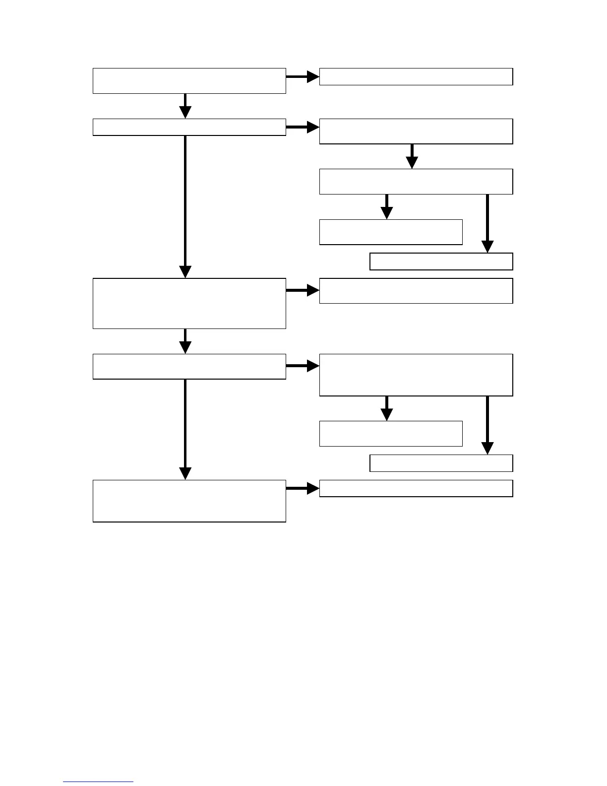
5.3 Picture is not outputted normally. (SCART)
NG
OK
NG OK
NG
OK
NG
OK
NG
OK
OK
OK
NG
NG
Are the E+6V and SW+12 voltage lines of
JV05 normal?
Is the +5VV line of QE01 normal?
Are the video signals inputted to each pin
of QE01 and QE02?
QE01: 8pin=Y, 9pin=V, 11pin=C,
14pin=R,QE02: 10pin=B, 12pin=G
Are the video signals inputted to each pin
of QE02? 4pin=V/Y, 14pin=C/R
Are the video signals outputted to each pin
of QE02?
16pin=C/R, 18pin=R, 20pin=B, 23pin=V/Y
Refer to “1. POWER SUPPLY PCB”.
Check the output voltage of QV91.
+5V
Check the QV91 (1pin) level.
1pin=H
Refer to “3.1 Check the panel
microprocessor”.
Replace QV91.
Refer to “3.4 Check the DIGITAL VEDEO
OUTPUT”.
Check the signal level of QE01 (12pin).
RGB/VIDEO output=H, S-VIDEO
output=L
Refer to “3.2 Check the B/E
microprocessor”.
Replace QE01
Replace QE02.