
L
lisasloanAug 1, 2025
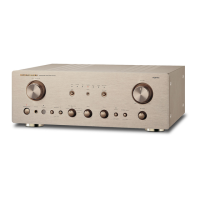
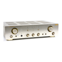
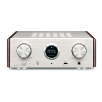
What to do if FLT-DISPLAY doesn't light on Marantz HD-AMP1/U1B/N1B/N1SG?
- Rrebecca64Aug 1, 2025
If the FLT-DISPLAY on your Marantz Amplifier doesn't light up, the suggested solution is to replace the SMPS PCB.
What to do if FLT-DISPLAY doesn't light on Marantz HD-AMP1/U1B/N1B/N1SG?
If the FLT-DISPLAY on your Marantz Amplifier doesn't light up, the suggested solution is to replace the SMPS PCB.
Explains how to use the manual's search and navigation features effectively.
Guide on using the 'Sign' function to add notes to the manual.
How to magnify specific areas of diagrams using keyboard and mouse.
Instructions for printing magnified parts of the manual with specific settings.
Using the Pan & Zoom tool for detailed viewing of diagrams.
Utilizing the Loupe Tool for magnified views of specific diagram sections.
Perform a leakage current check before returning the set to the customer.
Heed cautions for electric shock, disassembly, parts, and wire placement.
Verify all parts and wires are correctly placed after servicing.
Use designated parts with critical safety properties as indicated.
Pay attention to critical parts marked with ' ' for replacement.
Notes on ordering parts and unavailable items ('nsp').
Instructions for grounding human body and workbench for ESD protection.
Details on rated output, frequency response, SN, and harmonic distortion.
Information on power supply, consumption, and standby power.
Steps to initialize the unit after replacing components or PCBs.
Lists specific jigs and kits needed for firmware updates.
Instructions for removing the side panels by unscrewing them.
Instructions for removing the top cover by unscrewing it.
Steps to remove the front assembly by unscrewing and disconnecting.
Steps to remove the rear panel by unscrewing and disconnecting.
Instructions for removing the main PCB, including screws and connectors.
Steps to remove the amp module by unscrewing and disconnecting.
Steps to remove the digital PCB by unscrewing and disconnecting.
Instructions to remove the audio PCB by unscrewing and disconnecting.
Steps to remove the SMPS PCB by unscrewing and disconnecting.
Explains button combinations to enter various special modes.
Visual guide showing the sequence of entering and navigating service modes.
Details the sequence of firmware versions displayed in this mode.
Explains how the display and LEDs behave in this mode.
Shows detected protection events and how to clear them.
Procedure to reset unit settings to factory defaults.
Instructions to set and test the auto standby function.
Steps for region setting resistor change and software rewrite.
Procedures for updating firmware after replacing key components.
Detailed steps including connecting, unzipping, file structure, insertion, operations, and cautions.
Details operations, checking firmware version, and troubleshooting.
Guide for installing and executing the flash loader software for the update.
Diagnoses and steps for when the FLT-DISPLAY does not illuminate.
Checks for power supply voltages related to common signals.
Checks audio signal path from analog/digital selection to speaker output.
Verifies audio signal and MUTE circuit for subwoofer output.
Verifies power supply and audio signal for analog inputs.
Verifies power supply and data signals for USB-A input.
Checks reset, data, and signal paths for USB-B input.
Verifies DIR input and I2S signal outputs for digital inputs.
Identifies test points on PCBs for measurements and waveforms.
Details ICs like UcD1020EM and CVISTM32F101ZE with functions.
Pin assignments and functions for PQ033DNA1ZPH and K24C16 ICs.
Block diagram and pinout for the PST8425NR IC.
Pin configurations and functions for multiple ICs.
Detailed pinout and functional description for the MLC3730 IC.
Pin configurations and descriptions for memory ICs.
Detailed pinout and functional description for the XS1-U8A-128-FB217 IC.
Pin functions and configurations for buffer and flash memory ICs.
Block diagram and detailed pin descriptions for the PCM9211PTR IC.
Pin configurations and functions for ADuM1285 isolator and EMP8020 regulator.
Detailed pin descriptions and power supply requirements for the ES9010K2M IC.
Pin assignments and functions for audio control ICs.
Pinouts, equivalent circuit, and electrical characteristics for IC81 and Q203.
Physical dimensions, pin connections, and pattern details for the display unit.
| Power Output (8 ohms) | 35 W |
|---|---|
| Input Sensitivity | 200 mV |
| Digital Inputs | USB-B / Optical / Coaxial |
| Analog Inputs | RCA |
| Headphone Output | Yes (with adjustable gain) |
| USB-B DSD Support | DSD 2.8MHz/5.6MHz |
| USB-B PCM Support | 192kHz/24-bit |
| Supported Audio Formats | MP3 / AAC |