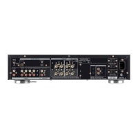
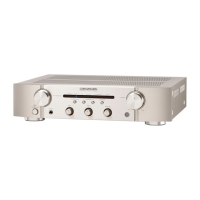
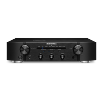
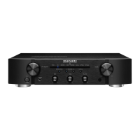
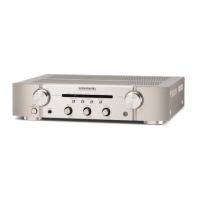
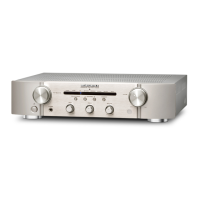
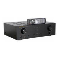
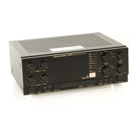
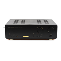
PM6002
Please use this service manual with referring to the user guide ( D.F.U. ) without fail.
Service
Manual
PM6002 /
N1B/N1S
Part no. 90M44CW855010
First Issue 2007.08
MZ
Integrated Amplifi er
TABLE OF CONTENTS
SECTION PAGE
1. TECHNICAL SPECIFICATIONS ........................................................................................... 1
2. DC OFFSET VOLTAGE ADJUSTMENT ................................................................................ 2
3. IDLING CURRENT ADJUSTMENT ...................................................................................... 2
4. BLOCK DIAGRAM ............................................................................................................... 3
5. WIRING DIAGRAM .............................................................................................................. 5
6. SCHEMATIC DIAGRAM ...................................................................................................... 7
7. PARTS LOCATION .............................................................................................................11
8. EXPLODED VIEW AND PARTS LIST ................................................................................17
9. MICROPROCESSOR AND IC DATA .................................................................................. 20
10. ELECTRICAL PARTS LIST .................................................................................................21
11. ABOUT REPLACE THE MICROPROCESSOR WITH A NEW ONE ...............................37