C
Cody BushAug 1, 2025
What to do if my Marantz Amplifier power won't turn on and the standby LED is flashing?
- MMr. Derek BrownAug 1, 2025
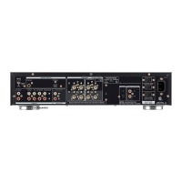
If the standby LED is flashing and your Marantz Amplifier won't turn on, begin by checking all connector insertions to ensure they are properly connected. Then verify that power is being supplied to the F8510. If the issue persists, inspect the STANDBY F8510 for broken wires, checking if power is reaching the coil of the POWER TRANS T0001. Also, check that power is being supplied to the D8001, D8101-8104, and D8201-8202. A broken D8001, D8101-8104, or D8201-8202 could also be the cause, so check the input level, speaker connection, and speaker resistance value. If power is supplied and the STANDBY LED repeats ON/OFF for 0.25 seconds each, it may indicate a damaged power amplifier or power circuit.