Do you have a question about the Marantz PM630 and is the answer not in the manual?
Overview of Marantz design philosophy and service approach.
Details the process and addresses for ordering Marantz replacement parts.
Intro, P.W. boards, test equipment, microcomputer, LED/Key matrix, and adjustment/voltage settings.
Details Phono Amp, Input Selector, Volume, Tone Control, and Main Amp sections.
Covers C-MOS digital ICs TC9151P/TC9152P and their pin functions.
Covers idling adjustment and voltage conversion for European models.
Illustrates the functional block diagram of the Marantz PM630 stereo pre-main amplifier.
Details the schematic and component layout for the Main Amp.
Provides schematic diagrams and component locations for the Tone Control Amplifier.
Details schematic diagrams and component locations for the Function/Volume Amplifier.
Shows schematic diagrams and component locations for the Logic Control Circuit.
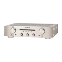
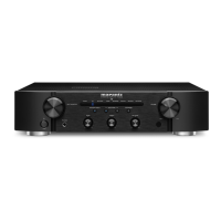
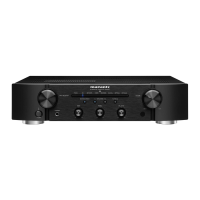
Provides schematic diagrams and component locations for the Front LED Switch Assembly.
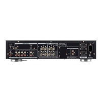
Schematics for Power Switch, Speaker LED, Output, Switch, Head Phone, and Fuse.
Exploded views and parts lists for Front Panel, Lid, General, Rear Panel, and Front Chassis.
Lists electrical parts for Tone Control, Function/Volume, Logic Control, and Front LED Switch assemblies.
Lists electrical parts for Speaker Switch, Speaker LED, Head Phone, Main Amplifier, and other components.
Provides technical specifications for the audio section, including power output and THD.
Details specifications for MM Cartridge, Aux Input, Output Voltage, and Impedance.
Provides general specifications including power requirements, dimensions, and weight.