9 10
LRCIN
DIN
BCKIN
CLKO
XTI
XTO
DGND
V
DD
V
CC
2R
AGND2R
EXT1R
EXT2R
V
OUT
R
AGND1
ML/DSD
MC/DM2
MD/DM1
MUTE
MODE
CKSL
DGND
V
DD
V
CC
2L
AGND2L
EXT1L
EXT2L
V
OUT
L
V
CC
1
1
2
3
4
5
6
7
8
9
10
11
12
13
14
28
27
26
25
24
23
22
21
20
19
18
17
16
15
Input
Interface
Digital
Filter
Mode
Control
Timing
Control
Noise
Shaper
5-Level ∆Σ DAC
Right
5-Level ∆Σ DAC
Left
Low-Pass
Filter-Left
Output
Amplifier
Left
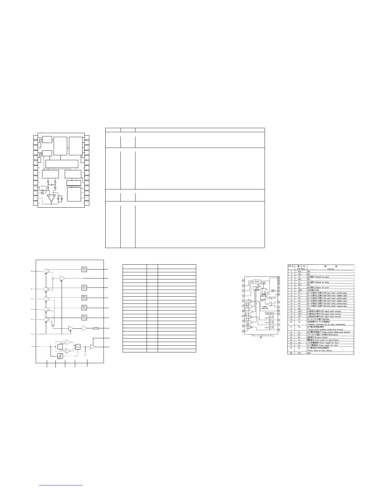
PIN NAME NUMBER FUNCTION
Input Interface Pins
LRCIN 1 Sample Rate Clock Input. Controls the update rate (fs).
DIN 2 Serial Data Input. MSB first, right justified format contains a frame of 16-bit or 20-bit data.
BCKIN 3 Bit Clock Input. Clocks in the data present on DIN input.
Mode Controls and Clock Signals
CLKO 4 Buffered Output of Oscillator. Equivalent to fs.
XTI 5 Oscillator Input (External Clock Input). For an internal clock, tie XTI to one side of the crystal oscillator. For an external clock,
tie XTI to the output of the chosen external clock.
XTO 6 Oscillator Output. When using the internal clock, tie to the opposite side (from pin 5) of the crystal oscillator. When using an
external clock, leave XTO open.
CKSL 23 System Clock Select. For 384fs, tie CKSL “High”. For 256fs, tie CKSL “Low”.
MODE 24 Operation Mode Select. For serial mode, tie MODE “High”. For parallel mode, tie MODE “Low”.
MUTE 25 Mute Control. To disable soft mute, tie MUTE “High”. To enable soft mute, tie MUTE “Low”.
MD/DM1 26 Mode Control for Data/De-emphasis. See “Mode Control Functions” on page 11.
MC/DM2 27 Mode Control for BCKIN/De-emphasis. See “Mode Control Functions” on page 11.
ML/DSD 28 Mode Control for WDCK/Double speed dubbing. See “Mode Control Functions” on page 11.
Analog Functions
V
OUT
R 13 Right Channel Analog Output.
V
OUT
L 16 Left Channel Analog Output.
Power Supply Connections
DGND 7, 22 Digital Ground.
V
DD
8, 21 Digital Power Supply (+5V).
V
CC
2R 9 Analog Power Supply (+5V), Right Channel DAC.
AGND2R 10 Analog Ground (DAC), Right Channel.
EXT1R 11 Output Amplifier Common, Right Channel. Bypass to ground with a 10µF capacitor.
EXT2R 12 Output Amplifier Bias, Right Channel. Connect to EXT1R.
AGND 14 Analog Ground.
V
CC
15 Analog Power Supply (+5V).
EXT2L 17 Output Amplifier Bias, Left Channel. Connect to EXT1L.
EXT1L 18 Output Amplifier Common, Left Channel. Bypass to ground with a 10µF capacitor.
AGND2L 19 Analog Ground (DAC), Left Channel.
V
CC
2L 20 Analog Power Supply (+5V), Left Channel DAC.
Q501 : PCM1710
FTC
OD5
OD1
OD4
OD3
OD2
RF
V
DDL
LO
I/V
V/I
V/I
V/I
VGAP
V
DDRF
AP5S
AP1S
AP4C
AP3C
AP2C
LG
MI
I/V
V
DD
GND
RF
GND
PWRON
1k5
SYMBOL PIN DESCRIPTION
OD2 1 output photo diode amplifier 2
OD3 2 output photo diode amplifier 3
OD4 3 output photo diode amplifier 4
OD5 4 output photo diode amplifier 5
OD1 5 output photo diode amplifier 1
PWRON 6 power on switch
RF 7 output data signal
V
DDRF
8 RF ampliÞer supply voltage
V
DD
9 supply voltage
GND 10 ground
GND
RF
11 ground RF amplifier
V
DDL
12 laser supply voltage
LO 13 current output for the laser diode
MI 14 Monitor input
n.c. 15 not connected
n.c. 16 not connected
AP1S 17 Input photo diode amplifier (satellite)
AP2C 18 Input photo diode amplifier (central)
n.c. 19 not connected
FTC 20 output fast track counting
LG 21 CD/CDRW gain switch
AP3C 22 Input photo diode amplifier (central)
AP5S 23 Input photo diode amplifier (satellite)
AP4C 24 Input photo diode amplifier (central)
Q101 : TZA1022
Q251 : BA6856FP