52
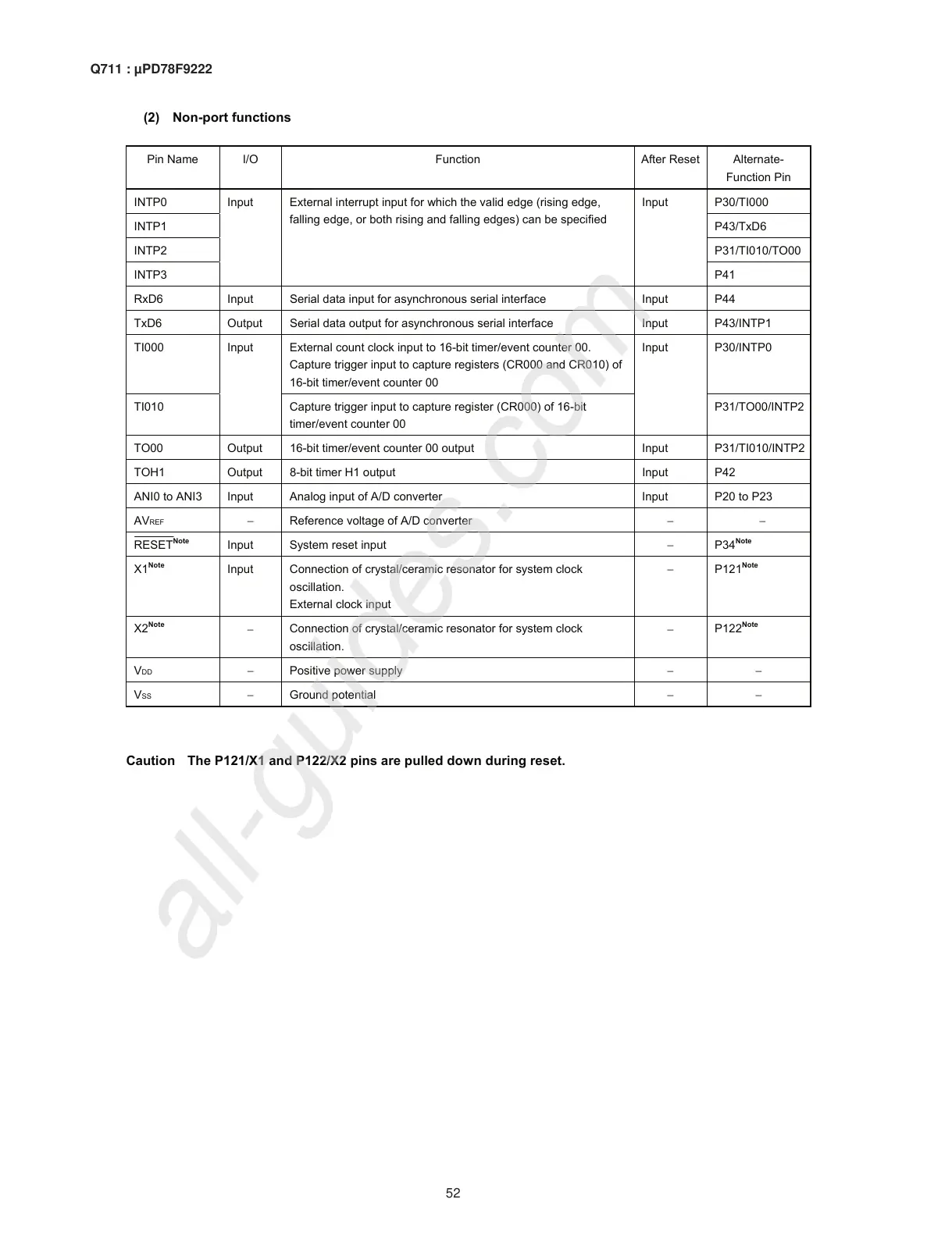
(2) Non-port functions
Pin Name I/O Function After Reset Alternate-
Function Pin
INTP0 P30/TI000
INTP1 P43/TxD6
INTP2 P31/TI010/TO00
INTP3
Input External interrupt input for which the valid edge (rising edge,
falling edge, or both rising and falling edges) can be specified
Input
P41
RxD6 Input Serial data input for asynchronous serial interface Input P44
TxD6 Output Serial data output for asynchronous serial interface Input P43/INTP1
TI000 External count clock input to 16-bit timer/event counter 00.
Capture trigger input to capture registers (CR000 and CR010) of
16-bit timer/event counter 00
P30/INTP0
TI010
Input
Capture trigger input to capture register (CR000) of 16-bit
timer/event counter 00
Input
P31/TO00/INTP2
TO00 Output 16-bit timer/event counter 00 output Input P31/TI010/INTP2
TOH1 Output 8-bit timer H1 output Input P42
ANI0 to ANI3 Input Analog input of A/D converter Input P20 to P23
AV
REF
−
Reference voltage of A/D converter
−−
RESET
Note
Input System reset input
−
P34
Note
X1
Note
Input Connection of crystal/ceramic resonator for system clock
oscillation.
External clock input
−
P121
Note
X2
Note
−
Connection of crystal/ceramic resonator for system clock
oscillation.
−
P122
Note
VDD
−
Positive power supply
−−
V
SS
−
Ground potential
−−
Caution The P121/X1 and P122/X2 pins are pulled down during reset.
Q711 : µPD78F9222

 Loading...