EasyManuals Logo

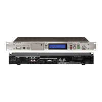
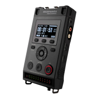
Marantz PMD570 Service Manual

Marantz PMD570
72 pages
To Next Page IconTo Next Page
To Previous Page IconTo Previous Page
Page #50 background imageLoading...
Page #50 background image
66
REFERENCR
+
-
CATHORD
ANODE
ANODE 2
V
REF
NC 1
NC 3
5 CATHORD
4 REFERENCR
(
NJM2327F/73AF
)
OSC1
OSC2
RS
R/W
COM
1
COM16
/ COMMK
E
VSS
VDD
RESET
VLCD
V5
DB3
DB0
DB7
DB4
4
8
8
7
7
7
7
60
17
60
17
8
8
88
8
55
60
7
8
4
R
B
RB
RB
RB
RB
V1
C1
V5OUT VC1
C1 C2 C2
V2
V3
V4
V5
SEG1
SEG60
CR OSC
Instruction
Decorder (ID)
Display Data Ram (DD RAM)
24x 8bits
Character
Generator
(CG RAM)
32x5 bits
I/O Buffer
Instruction Reg.
(
1R
)
DATA Reg.
(
1R
)
Busy
Flag
Cursor Blink
Cont.
60bit Latch
Segment
Driver
18bit
Shift Reg.
Common
Driver
Character
Generator
(CG RoM)
9600 bits
Parallel to serial
Converter
Voltage
Converter
60bit
Shift Reg.
RESET
Address
Counter
Timing
Gen.
Q820 : NJM2373-AF
QF01 : NJU6469LFG1

Other manuals for Marantz PMD570

Questions and Answers:

Question and Answer IconNeed help?

Do you have a question about the Marantz PMD570 and is the answer not in the manual?

Marantz PMD570 Specifications

General IconGeneral
BrandMarantz
ModelPMD570
CategoryRecording Equipment
LanguageEnglish

Related product manuals