3
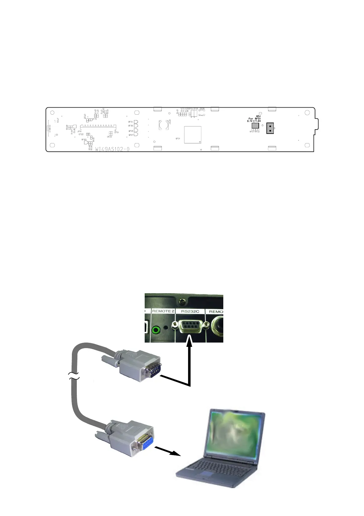
3. LCD CONTRAST ADJUSTMENT
1. Connect the TEST POINT (See below) with the tester.
2. Turn the variable resistor RF01 so that the reading of the
tester becomes 7.0 V ± 0.1 V and conferm the contrast of
the LCD becames maximum.
3.LCD輝度電圧調整
LCDモジュールとメイン基板(PF01)をペアーとして以下の調
整をおこなってください。
1.TESTPOINTJF02にテスターを接続し、輝度電圧を測
りながらボリューム RF01 の抵抗値を調整します。
2.LCDを正面から見て、コントラストが最大になることを確
認しながら輝度電圧を 7.0V±0.1V に調整します。
RF01
TEST POINT
JF02
PF01 FRONT LCD
4. Mainmicroprocessor(QU01)
アップデート方法
必要機器
・ WindowsPC(OS:Windows2000または WindowsXP)
で COMport のあるもの
・ RS232C ストレートケーブル(9pin メス
-
9pin オス)
・ マイコンアップデートディスク(*PMD570CDR)
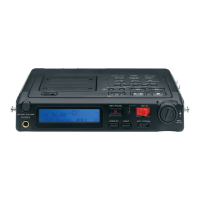
4.1.接続方法
1 PMD570とWindowsPCのCOMポートをRS232Cケー
ブルで接続します。
4. MAIN MICROPROCESSOR (QU01)
UPDATE PROCEDURE
Necessary Equipment
• Windows PC (Windows2000 or WindowsXP) with COM
port
• RS232C cable straight type (9pin female
-
9Pin male )
• Update Disc (*PMD570CDR)
4.1. Connection
1. Connect COM port of Windows PC and PMD570 with
RS232C cable.
PMD570 Rear Panel
RS232C Terminal
RC232C cable
Windows PC
COM Port