11
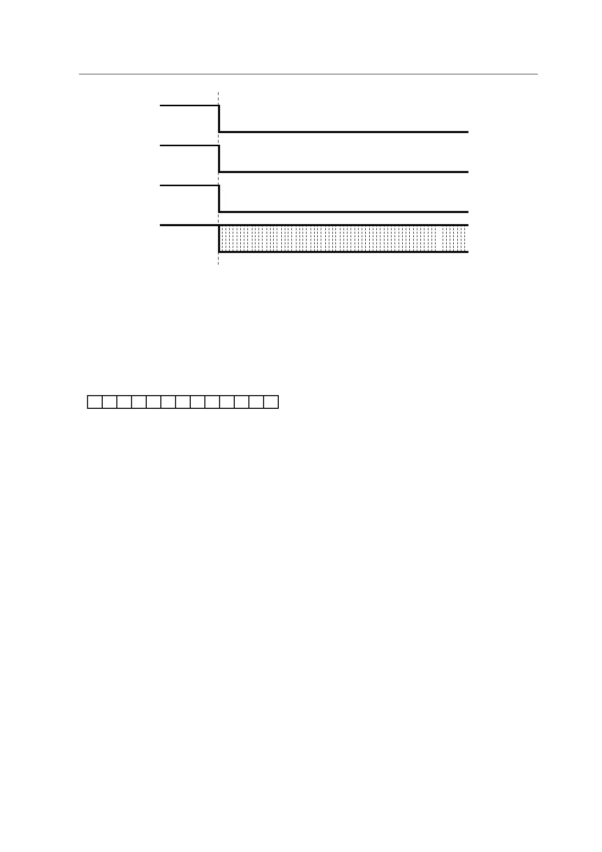
Power Line Fail
SPK Relay Relay off
STANDBY
STANDBY LED
STANDBY LED OFF
0.125sec blinking
CHECK DSP ROM
SR5002 : MULTI SPK + ATT + EXIT Press button 3sec
A set is broken in the flash state of the 0.125sec interval, so please never make the user do this release operation.
CHECK POINTS OF SCHEMATIC
1. Abnormality confirms whether to the +/- power supply for Power Amp.
2. Abnormality confirms whether to +/-12V power supply.
3. When trouble is not found in the power supply circuit, it is confirmed whether there are in the disconnection and the
detector circuit of the pattern of IC11 66pin (Power Line Fail) abnormalities.
5. Trouble in DSP Communication
• When the communication abnormality of DSP(IC27) and the microcomputer(IC11) is detected or inside contents of
ROM(IC40) of DSP unmatched, it display it.
1. Conform power supply voltage of IC27/IC40 Vcc/Vdd. When it is an abnormal voltage, the power supply is repaired.
2. It is confirmed that IC11 74pin(DSP DOUT Line) is normal at the time of the Power ON
3. It is confirmed that IC11 75pin(DSP DIN Line) is normal at the time of the Power ON
4. It is confirmed that IC11 76pin(DSP CLK Line) is normal at the time of the Power ON
5. It is confirmed that IC11 80pin(REQ1 Line) is normal at the time of the Power ON
6. It is confirmed that IC11 81pin(REQ2 Line) is normal at the time of the Power ON
7. When IC11 74pin-76pin and 80, 81 pin are abnormal, disconnection and defective solder etc. of the pattern are
confirmed