81
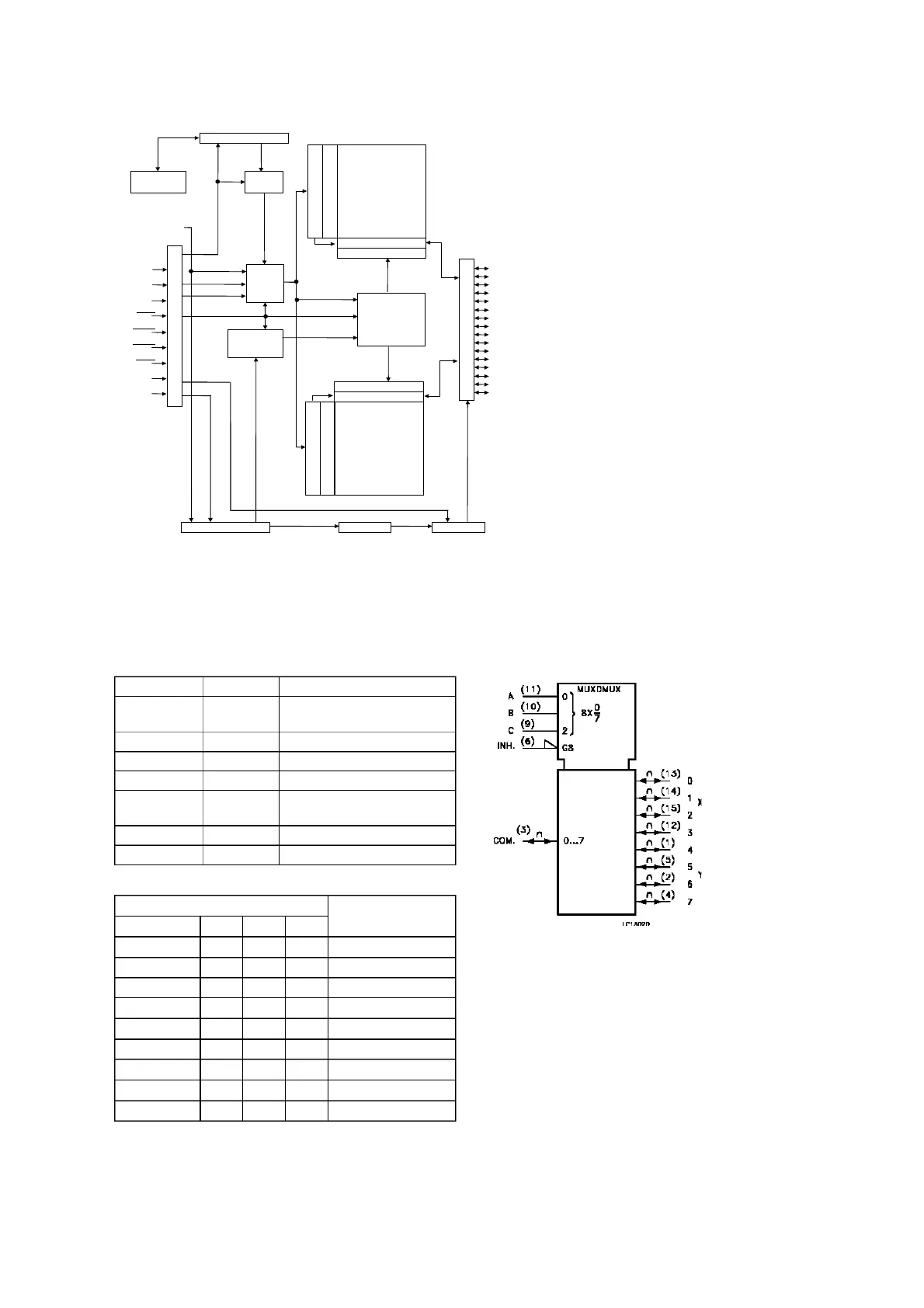
INPUT STATES
”ON” CHANNEL
INHIBIT C B A
LLLL 0
LLLH 1
LLHL 2
LLHH 3
LHLL 4
LHLH 5
LHHL 6
LHHH 7
H X X X NONE
X: DON’T CARE
PIN No SYMBOL NAME AND FUNCTION
3COM
OUT/IN
Common Output/input
6 INH INHIBIT Input
7V
EE
Negative Supply Voltage
11, 10, 9 A, B, C Select Inputs
13, 14, 15,
12, 1, 5, 2, 4
0 TO 7 Independent Input/Outputs
8 GND Ground (0V)
16 V
CC
Positive Supply Voltage
Column Addr.
Latch & Counter
Burst Length
Counter
Refresh
Interval Timer
Refresh
Counter
DQ0
DQ1
DQ2
DQ3
DQ4
DQ5
DQ6
DQ7
DQ8
DQ9
DQ10
DQ11
DQ12
DQ13
DQ14
DQ15
Address
Register
I/O ControlTest ModeMode Register
Self Refresh Counter
Column Decoder
Sense AMP & I/O gates
512Kx16
Bank 0
Column Decoder
Sense AMP & I/O gates
512Kx16
Bank 1
RAS
CAS
CS
WE
UDQM
LDQM
CKE
Precharge
Overflow
Column Active
Row Active
Address[0:10]
CLK
BA(A11)
State Machine
Row Decoder
Row Addr. Latch/Predecoder
Auto/Self Refresh
Ref. Addr.[0:11]
Data Input/Output Buffers
Row Addr. Latch/Predecoder
IC41 : 57V161610ET7
IC42 : M74HC4051RM