67
Power and Ground Pins
Pin Name Pin # Type Description
VCC 6,38,67 Power Digital Core VCC, must be set to 3.3V.
GND 5,39,68 Ground Digital Core GND.
OVCC 18,29,43,57,78 Power Output VCC, must be set to 3.3V.
OGND 19,28,45,58,76 Ground Output GND.
AVCC 82,84,88,95 Power Analog VCC must be set to 3.3V.
AGND 79,83,87,89,92 Ground Analog GND.
PVCC 97 Power PLL Analog VCC must be set to 3.3V.
PGND 98 Ground PLL Analog GND.
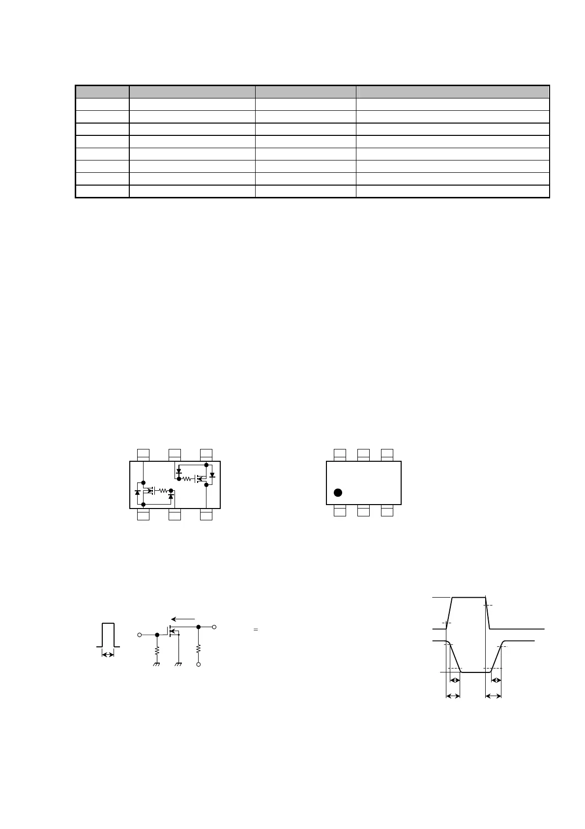
IC11 IC12 (DVI PCB) : SiI 1161
Equivalent Circuit
(top view)
Marking
(Q1, Q2 common)
Switching Time Test Circuit
(a) Test circuit (b) V
IN
V
GS
(c) V
OUT
V
DS
K
654
321
Q1
6 5
3
4
21
Q2
V
DD
= 1.5 V
D.U.
1%
V
IN
: t
r
, t
f
< 5 ns
(Z
out
= 50 W)
Common Source
Ta = 25°C
1.5 V
90%
10%
90%
10%
0
V
DD
V
DS (ON)
t
on
t
off
t
r
t
f
IN
50 9
OUT
I
D
1.5 V
10 ms
V
DD
R
L
V
IN
0
Q121 (VIDEO CONVERTER PCB) : HN1K05FU