EasyManua.ls Logo

Marantz SUPERSCOPE CD-320 - 5 B-10 Record-Playback Frequency Response Adjustment; 5 B-11 Bias Trap Adjustment; 5 B-12 Adjusting the Dolby Circuit

Marantz SUPERSCOPE CD-320
41 pages
Print Icon
To Next Page IconTo Next Page
To Previous Page IconTo Previous Page
Loading...
co-320
5810
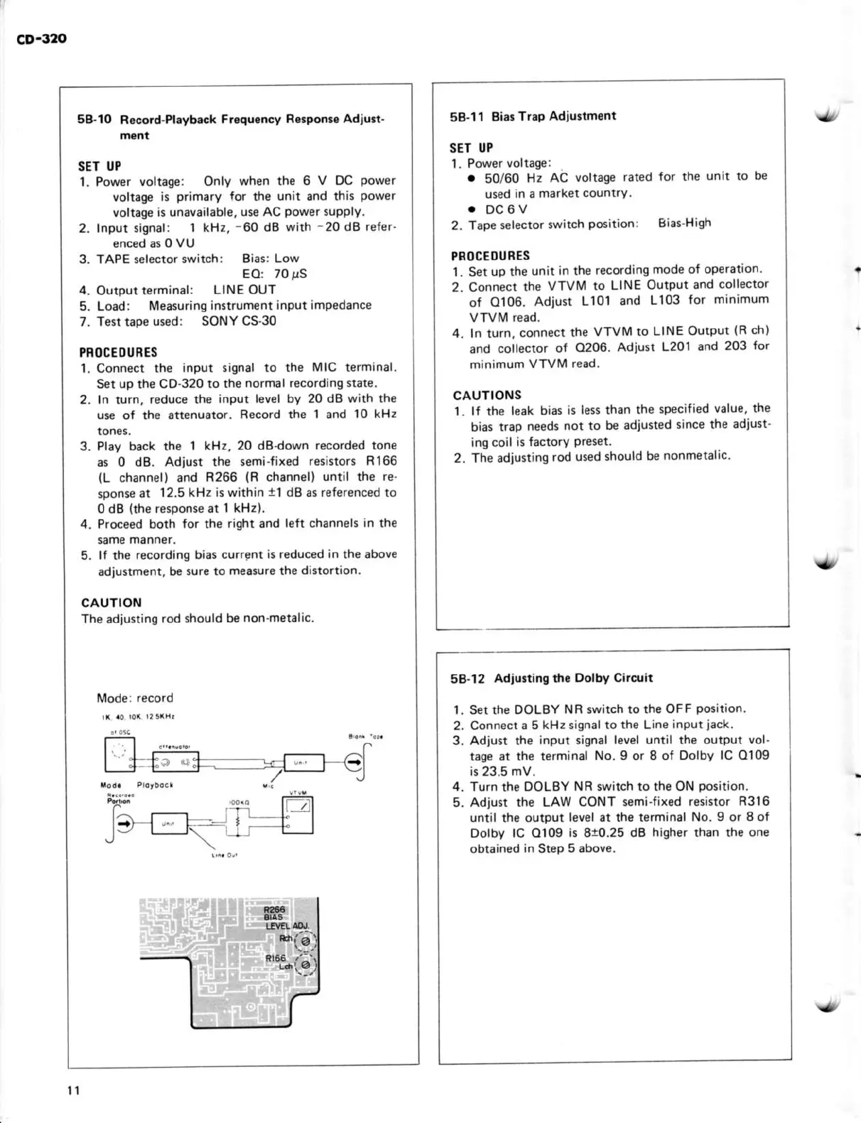
Record.Plâybâck
F.rquoncy
Rêspoff. Adiu3t-
SET U?
1. Power vokage: Only
when the 6
V
Oc
power
voltag€
is
primafy for
thê
unit
.nd
fik
power
vottage is unavâilable,
ure AC
power
supply.
2. Input
signal: 1 kHz,
-60
dB with 20
dB refer
enced ar 0
vU
3. TAPE selector
swirch: Eiat: Low
EO:
70!S
4.
Output terminâl:
LINE OUT
5. Load:
Mۉsuring
instrument input impedance
7. Test tape used: SONY
CS.30
PROCEOUNES
L Conn€ct the
input signâl to the
MIC terminal.
Set up the CO-32010
the
normalrecording stâte.
2. ln tuh,
reduce the
input levêl by 20 dB wiû the
use
of the
at1enuator.
Record the 1 and 10
kHz
3. Play back the
I kHz, 20 dBdown
recorded tone
âs 0 d8. Adjust
rhe semiJixed
resistorr Rl66
(L
channel) and
R266
(R
chânnel)
until rhe re'
sponse
at
12.5 kHz
is
wilhin
1l
dB
as
rel€renced
to
0 dB
khe
response at
I
kHz).
4. Proceed both
for
the
right ând left chânnels
in the
5. ll the recording
biat cutrgnt
is reduced in the above
adjustmenr,
be sure to
mea.ure the dattortion.
CAUTION
The âdiurting
rod should bê
non_met3lac.
.*i
I f ïr
"F
t= t Fl
/-1
5Bll
Bia!
Trôp Adiunmont
SET U?
.
50/60
tlz AC
voltâge
rated for the
unil to
be
used
in a
mârket coutrtrY.
.
oc6v
2.
Tape selector
switch
potition:
Biat
High
PBOCEOUEES
1. Set up the
unit
in rhe recording
mode ol operation
2. Co.nect
fie
VTVM to
LINE Output
ând
collector
of O106.
Adiust
Ll01 and
L103
lor
minimum
4.
In turn,
connect
$e
VTViI to
LINE Outpur
(R
ch)
and
collector
of 0206.
Adiust
L201 aôd
203
lor
minimum
VTVIV read.
cauTtoNs
1.
lf
the
leak bias
is
lest thân the
specilied
value, tbe
bias
trap
need3
not
to
be adiuited
since
the ad,ust-
ing coil
is fôctory
Preset.
2. The àdiusring
rod used thould
be
nonmetâlrc
-
-
5a-12
Adju3rin! $. Dolby
cncuit
l. S€t the
DOLBY NR rwitch to
the OFF
position.
2.
Connect a 5
kHzsisnalto the Line
input
iack.
3. Adiùit
the input signal
levêl until thé outpul vol-
tâqÉ ât the terminal
No.9 or I of Dolby lC 0109
is 23.5 mV.
4. Tu,n rhe DOLBY
NB
lwitch lo
lhe
ON
posit,on.
5. Adjust th€ LAw
CONT semiJixed
retistor F3l6
until thé output
level at th6 terminal
No. I or 8 of
Dolby lC Ol09
is
8!0.25
dB higher than th€ one
obtained
in
Stèp
5 above.
ll

Table of Contents