3
MOUNTING
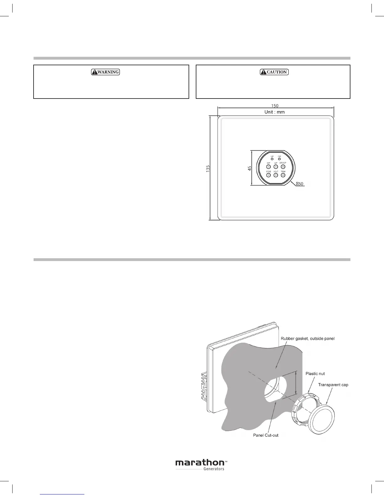
The PM500 is mounted through a keyed hole in the
generator conduit box and secured with a plastic
mounting nut.
The PM500 should be mounted directly to the
conduit box panel with the rubber gasket positioned
between the outside of the conduit box panel and the
mounting nut.
Protect front panel adjustment pots by installing clear
or black plastic cover.
Mounting nut torque is 26 – 43 lbf-in.
Refer to the Figure 1 for dimensions.
DO NOT megger or high-pot the generator with the regula-
tor connected. DO NOT high-pot the regulator. All voltage
readings are to be taken with an average-reading voltmeter.
Installation
Wiring and Connections
EXCITER FIELD POWER CIRCUIT
The exciter field resistance must be ≥ 9 ohms.
If the exciter field resistance is less than 9 ohms and
the full load field current does not exceed 3.5 amps,
add a resistor in series of sufficient wattage to increase
the total resistance to 9 ohms.
Connect the generator F+ (F1) field lead to the regu-
lator F+ terminal. Connect the generator F- (F2) field
lead to the regulator F- terminal. Refer to Figure 3 for
typical connection points.
POWER INPUT CIRCUIT
The PM500 is designed to be powered by a PMG and
capacitor. A 7.5µƒ capacitor is to be connected in
parallel between the PMG leads and the regulator
power input terminals.
The regulator power input terminals are labeled
P1 and P2. Connect leads P1 and P2 to the capacitor
terminals.
When the PMG system is not functional, the PM500
may be shunt powered from the generator output
leads. Connect regulator terminal P1 & P2 to genera-
tor leads that will provide 240Vac output. The capaci-
tor is not used when the PM500 is shunt powered.
Refer to Figure 3 for typical connection points.
TO PREVENT PERSONAL INJURY OR EQUIPMENT
DAMAGE, ONLY QUALIFIED PERSONNEL SHOULD
INSTALL, OPERATE OR SERVICE THIS DEVICE.
Figure 1
Figure 2