5
Wiring and Connections (cont’d)
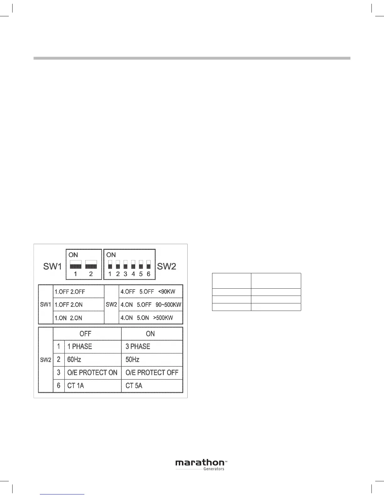
DIP SWITCH PROGRAMMING
Eight DIP switches located on the back of the regu-
lator must be set appropriately for correct generator
operation. Refer to Figure 5.
SW1 – Sets regulator sensing range
SW1-1
: OFF :
SW1-2
: OFF : Volts ≤ 240Vac
SW1-1
: OFF :
SW1-2
: ON : Volts ≤ 440Vac
SW1-1
: ON :
SW1-2
: ON : Volts ≤ 600Vac
SW2 – Configures multiple regulator functions:
Phase, Frequency, Over Excitation Protection, kW
Range and Paralleling CT range.
SW2-1
: OFF : Single Phase : ON : Three Phase
SW2-2
: OFF : 60Hz : ON : 50Hz
SW2-3
: OFF : Over Excitation Protection Enabled
SW2-3
: ON : Over Excitation Protection Disabled
SW2-4
: OFF :
SW2-5
: OFF : < 90kW
SW2-4
: ON :
SW2-5
: OFF :
90 - 500kW
SW2-4
: ON :
SW2-5
: ON : > 500kW
SW2-6
: OFF : 1A CT : ON : 5A CT
PROTECTION FUNCTIONS
The PM500 has built in protection functions for
Over Excitation, Under Frequency and Over Voltage
Protection.
Over Excitation
The Over Excitation function protects the PM500
and generator components in the event the excitation
system demands excessive levels of voltage and/or
current to maintain output.
The Over Excitation function will trip when excitation
output exceeds 190Vdc or 7Adc for more than 10 sec.
with 220Vac input power.
The Over Excitation O/E LED on the front panel
will be illuminated when the PM500 when the Over
Excitation system has tripped. Replace the fuse on the
back panel if required and inspect the generator. The
PM500 will reset when power is cycled
Under Frequency
Under Frequency protection allows the generator
voltage to decrease when the output frequency drops
below the Roll-Off point. This reduces the load on the
engine, allowing engine RPM to recover. This is normal
operation and no reset is required.
Over Voltage
The Over Voltage function will trigger when excessive
output voltage is detected:
When excessive output voltage is detected an internal
SCR will short power output causing the input fuse on
the back panel to blow. Over Voltage protection is a
single use system.
To reset the PM500 for operation without Over
Voltage protection, disconnect the OVP jumper on
the back panel and replace the input fuse located on
the back panel. It is recommended that the PM500 be
replaced as soon as feasible.
≤ 240VAC
≤ 440VAC
≤ 600VAC
Output (V)
Trip (V)
Instantaneous
≤ 240 310 – 330
≤ 440 560 – 580
≤ 600 700 – 720
Figure 5
 Loading...