EasyManua.ls Logo

Marathon TSC 900 User Manual

Marathon TSC 900
96 pages
To Next Page IconTo Next Page
Page #1 background imageLoading...
Page #1 background image
9087A 198
th
Street, Langley, BC Canada V1M 3B1 Telephone (604) 888-0110
Telefax (604) 888-3381 E-Mail: info@thomsonps.com www.thomsonps.com
TSC 900
TRANSFER SWITCH CONTROLLER
INSTALLATION, OPERATING &
SERVICE MANUAL
Part ID 013190 PM0151 REV 1 15/10/08

Table of Contents

Questions and Answers:

Marathon TSC 900 Specifications

General IconGeneral
BrandMarathon
ModelTSC 900
CategoryController
LanguageEnglish

Summary

Introduction to TSC 900 Controller

Product Revision History

Provides a historical summary of changes made to the TSC 900 product since its original release.

General Description of TSC 900

Details the TSC 900 controller's 32-bit microprocessor design and DSP technology for accurate sensing.

TSC 900 Installation Guide

General Installation Information

Provides general installation guidelines and notes on electrical regulations for the TSC 900.

Notes for Installer

Important notes and warnings for installers regarding system voltage confirmation and qualified personnel.

AC Voltage Sensing Input

Details the acceptable AC voltage sensing input ranges and system types for the TSC 900.

AC Current Sensing Input

Explains the requirements for AC current sensing inputs and safety precautions.

AC Control Power Input

Specifies the AC control power input voltage and VA requirements for the TSC 900.

Auxiliary DC Control Power Input

Describes the optional 24Vdc auxiliary control power input for specific applications.

Programmable Inputs

Details the 16 programmable inputs and their activation methods.

Controller Outputs

Lists the types and specifications of the output circuits provided by the TSC 900.

External ATS Control Wiring

Discusses minimum requirements for external ATS control wiring and wire sizes.

Remote Start Contact Field Wiring

Provides guidelines for wiring remote start contacts to avoid controller malfunction.

Communication Cable Installation

Guidelines for routing communication cables to protect against electrical interference.

Dielectric Testing Precautions

Warns against performing high voltage dielectric testing with the controller connected.

TSC 900 Controller Description

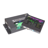
Graphical HMI Controller (GHC) Display Hardware

Describes the GHC display hardware, its interconnection, and key features and ports.

Switch Control Unit (SCU) Hardware

Details the SCU internal PCB and lists main I/O connections.

ATS Operation Mode Descriptions

Explains the main operating modes of the TSC 900 ATS: AUTO, OFF, MANUAL, TEST, etc.

Open Transition Transfer Sequence

Details the automatic sequence of operation for open transition transfers.

Closed Transition Transfer Sequence

Explains the sequence of operation for closed transition transfers.

Automatic Load Shed Operation

Describes automatic load shedding based on frequency, power, or utility failure.

Test Mode Operations

Covers ON LOAD TEST and OFF LOAD TEST procedures for the ATS.

Abnormal Sequence of Operation

Details sequences for generator failure, transfer switch failure, and service entrance ATS.

GHC Display Main Menu Pages

Introduces the main menu pages available on the GHC display software.

Home Page Description

Describes the Home Page as a summary control and monitoring screen for the ATS.

Utility Metering Page

Provides detailed voltage and frequency metering data for the utility supply.

Generator Metering Page

Provides detailed voltage and frequency metering data for the generator supply.

Load Metering Page

Provides voltage, current, and power metering data for the ATS load bus.

Alarms Page Functionality

Displays active alarms and provides a function to reset all activated alarms.

Alarms Log Page

Shows time/date stamped information regarding occurred alarms.

Events Log Page

Shows time/date stamped information regarding occurred events.

Sync Page for In-Sync Transfers

Displays synchroscope information for closed or fast in-sync transfer applications.

Scheduler Page for Exercise Events

Used to set on load or off-load exercise events using calendar-based scheduling.

Settings Page for Configuration

Used for programming timers, voltage/frequency set points, and I/O mapping.

System Page for Application Settings

Used for viewing or programming specific settings based on the application.

Import/Export Database Functionality

For importing program settings, firmware, or backing up controller settings.

Time and Date Setup

For changing the TSC 900 real-time clock settings to match the installed location.

Manage Users for Security

Shows existing controller users and allows adding or editing new users.

System Information Display

Displays current firmware versions installed on the TSC 900 controller.

Programmable Input Mapping

Shows how the TSC 900 programmable digital inputs are configured.

Programmable Output Mapping

Shows how the TSC 900 programmable relay outputs are configured.

Logs for Data Recording

Displays available data logs that the TSC 900 controller is logging on a real-time basis.

COM Status for Communication Ports

Shows the status of the TSC 900 controller's Serial (RS232) or TCP (Ethernet) ports.

TSC 900 Operating Instructions

GHC Screen Page Navigation

Explains the two methods for manually selecting a desired screen page on the GHC display.

On Load Test Instructions

Details how to perform an ON LOAD TEST by simulating a utility power failure.

Off Load Test Instructions

Details how to perform an OFF LOAD TEST to run the generator without load transfer.

Timed Test Instruction

Provides the procedure for performing a TIMED TEST including test type and duration.

Open/Closed Transition Transfer Operation

Describes different Open or Closed Transition Transfer operational features available.

Open Transition In-Sync Transfer (Model X)

Details the operation of Open Transition In-sync Transfer when ATS Model X feature is used.

Closed Transition Operation (Model 3 & 4)

Explains the operation of Closed Transition Transfer features for Models 3 and 4.

Transfer Fail Alarm Reset Procedure

Explains how to reset a 'Transfer Fail' alarm and determine the cause.

Timer Bypass Functionality

Describes how to temporarily bypass automatic sequencing time delays during testing.

Manual Utility Retransfer Control

Details how an operator can manually initiate a re-transfer to the utility supply.

Service Disconnect Mode Operation

Describes the logic and operation when the Service Disconnect switch is activated.

Phase Unbalance Protection Alarm Reset

Explains how to reset phase unbalance alarms and re-transfer logic.

Transfer Halted Alarm Reset

Details how to reset a 'Transfer Halted' alarm condition manually.

TSC 900 Programming Instructions

Password Security Description (Users Admin)

Describes user access levels, groups, and default security settings.

User Login Procedure

Details the step-by-step procedure for logging into the TSC 900 controller.

Administrator Password Management

Explains how an administrator can add, edit, or manage ATS user accounts.

System Time and Date Adjustment

Details the procedure for adjusting the TSC 900 controller's internal time clock.

Voltage Change Procedure

Explains how to change the system voltage setting via software programming.

Exercise Timer Setup

Describes the built-in calendar-based programmable exercise timer.

Adding New Exercise Schedule Event

Details how to create new exercise schedule events using the Scheduler page.

Editing Existing Exercise Schedule Event

Details how to edit existing exercise schedule events via the Scheduler page.

Programmable Input Mapping

Explains how to map the TSC 900's programmable digital inputs to parameters.

Programmable Output Mapping

Explains how to map the TSC 900's programmable relay outputs to parameters.

System Phases Configuration

Sets the power distribution system configuration (single or 3 phase).

System Voltage Configuration

Sets the nominal system voltage, expressed in phase-to-phase voltage.

System Frequency Configuration

Sets the nominal system frequency to either 50Hz or 60Hz.

Phase Rotation Reversed Setting

Configures the phase rotation system (Positive/Negative) for correct operation.

Rated Generator Power Setting

Sets the 100% power rating of the connected Generator in kilowatts.

CT Ratio (Current Transformer)

Sets the specific ratio of the CT size being used for load bus current transformers.

PT Ratio (Potential Transformer)

Sets the transformer ratio for voltage sensing wiring connections.

Load Name Configuration

Configures a unique name to be displayed in place of the text 'Load'.

Source 1 (Utility) Name Configuration

Configures a unique name to be displayed in place of the text 'Source 1'.

Source 2 (Gen) Name Configuration

Configures a unique name to be displayed in place of the text 'Source 2'.

Application Model Display

Displays the ATS application model type; this parameter is read-only.

Switch Operation Display

Displays the Switch Operation type; this parameter is read-only.

Switch Model Display

Displays the Switch Model type (e.g., ATS Mechanism S, T, or ICS); read-only.

Transfer Switch Mechanism Operation Time

Sets the time in milliseconds for ATS mechanism operation to close a power switching device.

Option Settings Overview

Introduces the various options that can be set depending on the controller type.

Current Metering Option

Enables current metering if the ATS was purchased with LPM or CT kit option.

Gen (Source 2) Commit to Transfer

Feature allowing two functional settings for committing to transfer to generator.

Enable Load Shed on Under Frequency

Enables load shedding logic based on load frequency threshold set points.

Enable Load Shed on Over Power

Enables load shedding logic based on load power (kW) threshold set points.

Halt Operation on Reversed Source

Prevents transfer between sources unless phase sequences match.

Enable Fail to Unload Alarm (CTTS Model 4)

Available with Closed Transition soft-load option; alarms if source fails to unload.

Trip Utility on Closed Transition Inhibit

Trips utility power switching device if inhibit signal is activated during closed transition.

Halt Transfer on Fail to External Sync Check

Controls how the external automatic synchronizer initiate output is controlled.

Manual Utility Retransfer Control

Allows operator-initiated re-transfer sequence to occur when utility power returns.

Force Transfer Feature

Allows ATS to automatically force transfer to alternate source upon abnormal condition.

GHC Sleep Mode Timeout

Sets the timeout for the GHC display to enter sleep mode to preserve lifetime.

Load Power Metering Option

Enables load power metering display on the GHC if LPM option is purchased.

Modbus RTU Communication

Enables the Modbus serial (RTU) communication option for the GHC.

Modbus TCP/IP Communication

Enables the Modbus TCP/IP Ethernet communication option for the GHC.

Enable Security Bypass

Allows ATS operation without security login; recommended to disable post-commissioning.

Fail to Auto Sync Alarm

Posts an alarm if sources fail to auto synchronize after timer expiry.

Open Transition In-Sync Transfer (ATS Model X)

Configures Open Transition In-sync transfer operation based on ATS Model X.

Closed Transition Transfer (CTTS Model 3 & 4)

Configures Closed Transition transfer operation for CTTS Models 3 and 4.

Neutral Delay Bypass Setting

Allows bypassing the neutral delay timer period under specific conditions.

Revert to Open Transition Setting

Selects how ATS operates if closed transition transfer fails to achieve 'in-sync'.

Enable Transfers to Utility

Permits or inhibits the transfer switch from transferring to the Utility position.

Enable Transfers to Generator

Permits or inhibits the transfer switch from transferring to the Generator position.

Extended Parallel Transfer (CTTS Model 4)

Allows ATS operation in Extended Parallel mode if feature is set to 'YES'.

Delay Settings Overview

Introduces the various programmable time delay features available for the TSC 900.

Utility Return Delay

Sets the delay period after utility supply returns within limits following a failure.

Gen Cool Down Delay

Sets the generator cool down period after the load has transferred from generator supply.

Gen Start Delay

Sets the generator start signal initiation delay following expiry of the start delay timer.

Gen Warm Up Delay

Sets the generator warm-up delay timer for transfer to generator supply.

Gen Commit to Transfer Delay

Sets delay for generator to transfer on load if 'commit to transfer' feature is enabled.

Depart Delay Setting

Introduces delay before 'departing' from current source to alternate source.

Transfer Fail Delay

Activates a fail alarm if transfer switch fails to transfer within the set delay.

Transfer Max Error Condition Delay

Activates fail alarm if transfer switch fails to transfer during abnormal sequence.

Timer Guard Delay

Provides delay between open and close signals for mechanisms with separate coils.

Transfer Find Neutral Delay

Ensures mechanism moves to neutral position when load voltage is unavailable.

Transfer Neutral Delay

Sets neutral delay time when both power-switching devices are open during transfer.

Transfer Pre-Delay (LDC)

Initiates a pre-transfer delay upon impending transfer when both sources are available.

Transfer Post Delay (LDC)

Initiates a post-transfer timer immediately following a transfer in either direction.

Disconnection Resume Time

Suspends actions for a set time when returning to Automatic mode for state resumption.

Load Shed Initiate Delay

Activates load shed output to shed non-essential loads upon transfer to Generator.

Load Shed Unshed Delay

Starts timing when load shed condition returns to normal, allowing re-energizing loads.

Trip Retry On/Off Pulse Time (SRC1&2)

Sets duration for on/off pulse signal to re-open a power switching device that failed to trip.

Trip Retry Duration Timer (SRC1&2)

Sets duration for retry attempt cycles if a power switching device fails to open.

Close Retry On/Off Pulse Time (SRC1&2)

Sets duration for on/off pulse signal to re-close a power switching device that failed to close.

Close Retry Duration Timer (SRC1&2)

Sets duration for retry attempt cycles if a power switching device fails to close.

Utility/Gen Set Points (Voltage/Frequency)

Provides programmable set points for over/under voltage and frequency sensing.

Under Voltage Delay (Dropout)

Sets the under voltage time delay for the source in seconds.

Under Voltage Dropout

Sets the under voltage drop-out set point as a percentage of nominal system voltage.

Under Voltage Pickup

Sets the under voltage pick-up set point as a percentage of nominal system voltage.

Over Voltage Delay (Pickup)

Sets the over voltage time delay for the source in seconds.

Over Voltage Dropout

Sets the over voltage drop-out set point as a percentage of nominal system voltage.

Over Voltage Pickup

Sets the over voltage pick-up set point as a percentage of nominal system voltage.

Unbalanced Voltage Latch

Affects retransfer sequence following an abnormal phase balance condition.

Phase Unbalance Delay (Pickup)

Sets the source phase unbalance time delay in seconds.

Phase Unbalance Drop Out

Sets phase unbalance drop-out set point as percentage of nominal negative sequence voltage.

Phase Unbalance Pick Up

Sets phase unbalance pick-up set point as percentage of nominal negative sequence voltage.

Under Frequency Delay (Dropout)

Sets the utility under frequency time delay in seconds.

Under Frequency Dropout

Sets under frequency drop-out set point as percentage of nominal system frequency.

Under Frequency Pickup

Sets under frequency pick-up set point as percentage of nominal system frequency.

Over Frequency Delay (Pickup)

Sets the source over frequency time delay in seconds.

Over Frequency Dropout

Sets over frequency drop-out set point as percentage of nominal system frequency.

Over Frequency Pickup

Sets over frequency pick-up set point as percentage of nominal system frequency.

Source Voltage Blackout Delay (Dropout)

Sets the source voltage blackout time delay in seconds.

Source Voltage Blackout Dropout

Sets source voltage blackout drop-out set point for neutral delay bypass.

Source Voltage Blackout Pickup

Sets source voltage blackout pick-up set point for neutral delay bypass.

Phase Reversal Delay (Pickup)

Sets the source phase reversal time delay in seconds.

Phase Reversal Drop Out

Sets phase reversal drop-out set point as percentage of nominal negative sequence voltage.

Phase Reversal Pick Up

Sets phase reversal pick-up set point as percentage of nominal negative sequence voltage.

Gen Must Start Delay

Sets maximum generator set start time delay in seconds for alarm feature.

Load Voltage Set Points

Sets load voltage points for transfer failure alarming or neutral delay bypass.

Load Voltage Blackout Delay (Dropout)

Sets the source load voltage blackout time delay in seconds.

Load Voltage Blackout Dropout

Sets load voltage blackout drop-out set point for neutral delay bypass.

Load Voltage Blackout Pickup

Sets load voltage blackout pick-up set point for neutral delay bypass.

Load Shed Set Frequency & Power Points

Configures frequency and power (kW) set points for automatic Load Shedding.

Load Shed Power (kW) Delay (Pickup)

Sets the load shed time delay in seconds.

Load Shed Power (kW) Drop Out

Sets load shed drop-out set point as percentage of rated generator power.

Load Shed Power (kW) Pick Up

Sets load shed pick-up set point as percentage of rated generator power.

Load Shed Frequency Pick Up

Sets load shed pick-up set point as percentage of nominal system frequency.

Load Shed Frequency Drop Out

Sets load shed drop-out set point as percentage of nominal system frequency.

In-Sync Transfer Set Points

Provides set points for in-sync transfer applications.

Closed Transition Max Overlap Timer

Sets adjustable time delay for maximum allowable parallel connection of two sources.

In-Sync Wait Delay

Sets time delay for achieving an in-sync condition for transfer operations.

External Sync Check Wait Delay

Allows time for auto-synchronizing process; triggers alarm if expired.

Source Frequency Differential Higher Threshold

Sets higher threshold for source frequency differential, blocking in-sync transfer.

Source Frequency Differential Lower Threshold

Sets lower threshold for source frequency differential, blocking in-sync transfer.

Source Voltage Differential Higher Threshold

Sets higher threshold for source voltage differential, blocking in-sync transfer.

Source Voltage Differential Lower Threshold

Sets lower threshold for source voltage differential, blocking in-sync transfer.

Fail to Unload Timer (CTTS Model 4)

Timer for normal soft-unload process after closed transition transfer.

Factory Default Programming

TSC 900 Typical Connection Diagram

TSC 900 Wiring Pin Connections

Troubleshooting Common Issues

Replacement Parts Information

Product Return Policy

Notes Section