TSC 900 TRANSFER SWITCH CONTROLLER
PM 151 REV 1 15/10/08 Thomson Power Systems
5.9. SYSTEM SETTINGS
Note: For specific device settings and ranges, refer to Section 6 - Factory Default
Programming.
The TSC 900 controller provides a flexible control system to allow specific operation for a wide
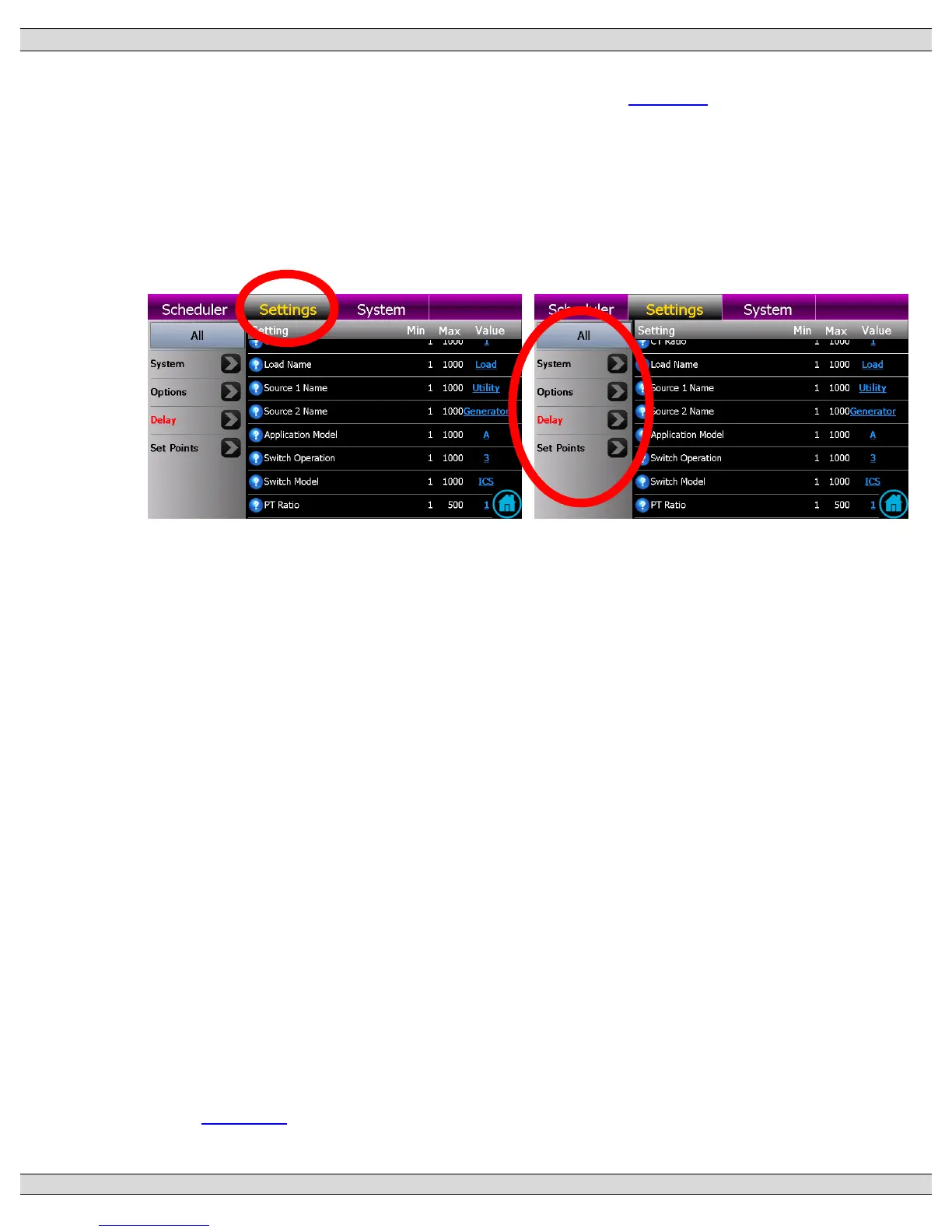
range of applications. To program settings, navigate to the “Settings” page as shown below.
Once on the Settings Page, select the group of Settings by adjusting the filter and scroll
through available list of functions as available.
5.9.1. SYSTEM PHASES
Set to match the power distribution system used on the automatic transfer switch (i.e.
either single phase or 3 phase system).
5.9.2. SYSTEM VOLTAGE
Set to nominal system voltage as expressed in “phase to phase” voltage. (E.g. A
347/600 volt system would be entered as “600”.) A drop down list of common voltages
appears when the blue underlined value is selected.
5.9.3. SYSTEM FREQUENCY
Set to nominal system frequency of either 50Hz or 60Hz.
5.9.4. PHASE ROTATION REVERSED
The Transfer switch is configured from the factory to operate on a normal A-B-C
(Positive) phase rotating system (i.e. Option Feature set for “NO”). This allows for
correct operation of voltage sensing and power metering option (if equipped) utilizing
the TSC 900’s internal symmetrical component algorithms (i.e. positive/negative/zero
sequence components). If the system is to operate on a C-B-A (Reverse) phase
rotating system, set this feature to “YES”. Note: Automatic transfers between sources
will be halted (i.e. blocked) if both source phase rotations are not matched. Refer to
Section 4.7 for further operating information on Transfer Halt conditions.