35
7) Connecting hoses
8) 2x hose clip
9) Filter container clip incl. screw and mother
10) Ratchet rod with pre–installed ller neck
11) 6x wreath blade
12) 2x set of screws, nuts and washers to attach the pump to the base
13) Base of ltration equipment
14) Pump
15) Drain valve – installed from the inside of the lter container
16) Sealing the container
17) Reduction for hose connection 38 mm
18) Transparent lid mat – Pre–installed on the pump
19) Transparent cover of the pump suction tank
20) 2x hose (only one is used)
21) Pump coarse prelter sieve
22) Transparent lid gasket
23) 2x O-ring
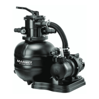
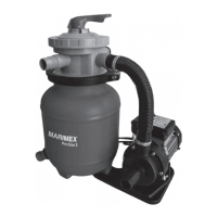
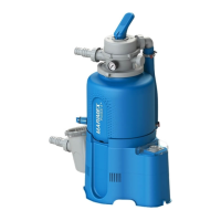
Specications ProStar Pro 4 ProStar Pro 6 ProStar Pro 8
Flow 4,5 m
3
/h 8,5 m
3
/h 9,5 m
3
/h
Tension 230 V/ 50Hz
Power consumption (W) 250 W 450 W 550 W
Cover IPX 4
Water temperature max. 35 °C
Sand rell max. 20 kg 35 kg 75 kg
Grain of lter sand 0,6–1,2 mm
Weight without lling 9,9 kg 11,6 kg 17,1 kg
Installation
Filtration device location
First, select the appropriate location for ltering. It should have asolid horizontal
substrate, be well accessible, protected from rain, sunlight and before ooding
with water. Avoid installing in wells, shafts, etc., as there is ahigh risk of ooding
the electric pump with water. Select aplace where at least 10 cm of air for engine
cooling will be located behind the pump motor. Also, there must be sucient space
for ltering and maintenance over ltration and around it. There must be asin-
gle–phase electric socket complying with the relevant ČSN standard. If you use the
extension cable, it must be H07RN-F type with across–sectional area of at least
1 mm
2
. It is recommended to use asuitable plate size under the lter unit (concre-
te, stoneware, etc.) and we recommend inserting arubber pad for vibration and
noise damping under the pump. For safety reasons, install the lter so that the
smallest distance from the edge of the pool is 2 m. Suction and return pipes / hose
EN
 Loading...