2011 Marin Rift Zone & Mount Vision Service Manual
2011 Marin Rift Zone & Mount Vision Service Manual2011 Marin Rift Zone & Mount Vision Service Manual
2011 Marin Rift Zone & Mount Vision Service Manual
Page 20
7.1: Removing the Rear Dropouts from the Swinging Arm.
Tools Required: 5mm Allen Key
6mm Allen Key
Both Left (4) and Right Hand (2) dropouts are a modular design, that can be replaced if
damaged. They are each attached to the Swinging Arm (3) by two bolts (1a & 1b), see fig.
8. To remove either Right Hand (2) or Left Hand (4) dropout using the 5mm Allen key for
the outside bolts (1a) and 6mm Allen key for the Inside Bolts (1b), undo both bolts, and
remove them from the assembly. The Dropout (2 & 4) should now be detached from the
Swinging Arm (3). Take care not to loose any of the components.
7.2: Assembling the Rear Dropouts onto the Swinging Arm
Tools Required: 5mm Allen Key
6mm Allen Key
Torque Wrench
Loctitie 638 retaining compound
It is important to make sure the Swinging Arm (3) and Dropouts (2 & 4) are clean and free
from mud and other dirt, which could prevent the Dropouts (2 & 4) and Swinging Arm (3)
from fitting together perfectly. Before assembling the bolts (1a & 1b), apply a small
amount of Loctite 638 retaining compound to the threads of each of the bolts (1a & 1b).
Next, assemble the parts as shown in Fig 8. making sure the Bolts (1a & 1b) are correctly
positioned as shown. Using the Torque Wrench, tighten the bolts (1a & 1b) to the correct
torque as specified in Section 8.0.
8.0: TORQUE SETTINGS
Torque explained: If no suitable Torque Wrench is available a Torque of 5 lbf.ft can be obtained by ap-
plying a force of 5lb, with a Spring Balance, to the end of a spanner, 1 Foot in length.
IMPORTANT: For all other torque settings, refer to the specific manufacturers information
bundled with this manual, or alternatively, refer to the specific manufacturers website for
further information.
Quad-Link 2 Suspension: Nm lbs.ft
M8 AeroSpace Nuts 18.0 +/- 2.0 13.3 +/- 1.5
Bearing Caps 5.0 +/- 0.5 3.7 +/- 0.4
Rear Dropout Assembly
Bolts 13.0 +/- 1.5 9.6 +/- 1.0
M5 Countersunk Capscrews 14 +/- 1.4 10.3 +/- 1.0
2011 Marin Rift Zone & Mount Vision Service Manual
2011 Marin Rift Zone & Mount Vision Service Manual2011 Marin Rift Zone & Mount Vision Service Manual
2011 Marin Rift Zone & Mount Vision Service Manual
Page 5
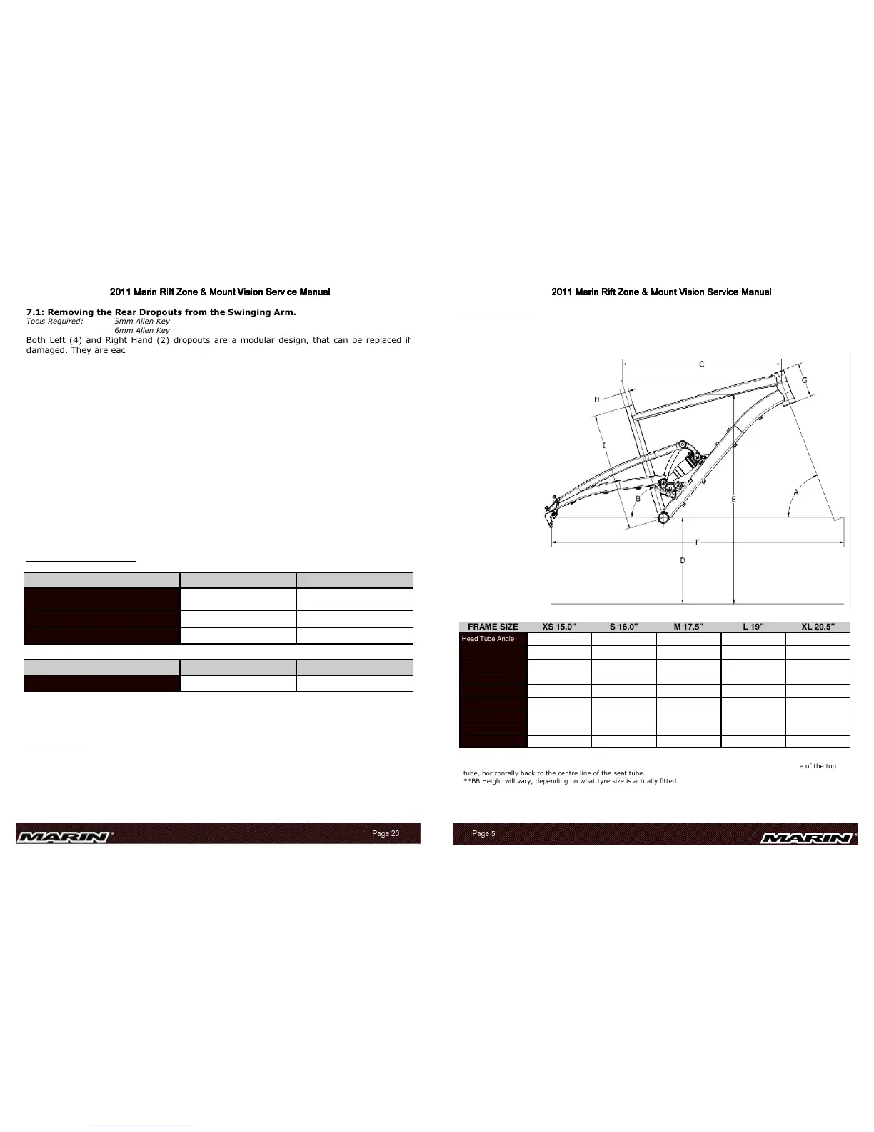
2.0: GEOMETRY
2.1: RIFT ZONE
Note: This is ‘Showroom’ Geometry, ie: without a rider sat on the bicycle.
*Top tube length is the distance from the point where the centre line of the head tube meets the centre line of the top
tube, horizontally back to the centre line of the seat tube.
**BB Height will vary, depending on what tyre size is actually fitted.
FRAME SIZE XS 15.0” S 16.0” M 17.5” L 19” XL 20.5”
Head Tube Angle (A) 69° 69° 69° 69° 69°
Seat Tube Angle (B) 72.7° 72.9° 73° 73.1° 73.4°
Top Tube* (C) 567.6mm / 22.3” 587.5mm / 23.1” 605mm / 23.8” 616mm / 24.3” 625.4mm / 24.6”
BB Height** (D) 329mm / 12.95” 328mm / 12.9” 327mm / 12.9” 326mm / 12.8” 324mm / 12.75”
Stand Over (E) 754mm / 29.7" 773mm / 30.4" 795mm / 31.3" 821mm / 32.3" 844mm / 33.2"
Wheel Base (F) 1069mm / 42.0" 1091mm / 42.95" 1110mm / 43.7" 1123mm / 44.0" 1130mm / 44.2"
Head Tube (G) 107.0mm / 4.2” 120.0mm / 4.7” 130.0mm / 5.1” 142.0mm / 5.6” 155.0mm / 6.1”
Seat Post Ø (H) 27.2mm / 1.07" 27.2mm / 1.07" 27.2mm / 1.07" 27.2mm / 1.07" 27.2mm / 1.07"
Seat Tube (I) 381.0mm / 15.0” 406.4mm / 16.0” 444.5mm / 17.5” 482.6mm / 19” 520.7mm / 20.5”
Fig.1: Geometry
 Loading...