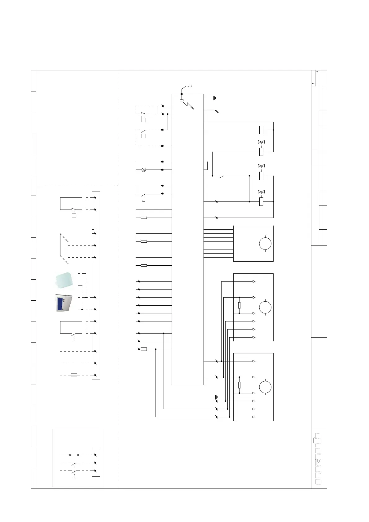
12.0 Schema electrica GS+ 100 EC
Pentru G+: vezi interiorul dispozitivului
1 2 3 4 5 6 7 8 9 10 11 12 13 14 15 16 17 18 19 20
GS+ 100 GAZ NATURAL
GS+ 15-100 PROPANE
EC-fan 230V
Get.
Gec.
Electric desen
J.W.
TvD
Data
Norm
28-1-2022
Numar
desenat
Grup
Art.nu.
WLV Tip
Versiunea
WLV-012250-RO
GS+
1.1
1
t e h n i c a c l i m a t i z r i i
R
Argus 864MN
Ts = 5sec
Tp = 30sec
Generator de curent
Senzor digital temperatura incaperii(optional)
Buton pentru resetare
pornit/oprit (factultativ)
Termostat de camera digital
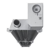
Ventilator gaze de combustie
Ionizare
Led pentru avertizare
Valva de gaz
Fitil
-
-
-
-
-
-
-
-
-
TT3
S2
S1
RT
VLV
IS
H1
GV1,GV2
F1,F2
1˜ 230V / 50Hz
Switch pentru izolareWS -
TT1
TT2
-
-
Senzor temperatura in apropiere de unitate
Sistem / maxima senzor temepratura
PE
Sitch presiune filtru(cand e folosit)-PF
Conexiuni externe
RT TT3
Max 8
unitati
BUS
factultativ
Motor pentru ventilator 1VM1 -
Motor pentru ventilator 2 (GS+80, GS+100)-VM2
Senzor apă de condensare (factultativ)-W
factultativfactultativ
K2 -
MK -
Releu
by-pass valva de gaz
Pentru generatoare de aer cald cu doua ventilatoare
(GS+80, GS+100)
*
*
GND
0-10V/
PWM
+10VdcPENL GND
0-10V/
PWM
+10VdcPENL
1
NPEL1
GV1 GV2
IS
T2
2
S1
01
J2-1
J2-3
J2-2
J16-7
J16-6
J5-10
J5-2
J5-12
J5-4
TT1
J5-11
J5-3
TT2.1
J13-2
J5-9
J5-1
J20-4
J20-3
1NPEL 3 42
+
-
H1S2
13 14
J13-4
J13-3
J12
J18-2
J18-1
5 6
F2
6.3A
PE
PE
L
L1
Conexiune cu switch izolator
1
2
WS
N
N
3
4
3 4 5 6NPEL
F1
16A
2 41 3
J5-14
J5-6
TT2.2
J13-5
J13-6
J9-2
J9-3
J9-4
J9-5
J9-6
J9-7
J9-1
J20-2
J20-1
7 8
W
J16-8
J16-1
87
PF
P
W
J16-4
11
14
K2
MK
A1
A2
K2
J6-2
J6-3
J2-4
VLV
L
N
-
HALL
+
PWM
1~
M
PE
11 12
VM1
1~
M
109
10KΩ 10KΩ
VM2
1~
M