5
NBN D51-003.
Gas supply and connection
Before installation, check that the local distribution conditions, gas type and pressure and the
current adjustment of the appliance all match. An approved gas stop cock must be tted to the inner
pipeline.
Flue gas route
Combustion air supply pipelines and combustion gas exhaust ducts should have as few bends as
possible; in general, ow resistance should be kept to a minimum and in all cases, the diameter
should be constant along the entire length. The exhaust duct may not rest on the heater, but should
be suspended efciently! If the ue gas exhaust duct passes along or through combustible walls or
oors, the duct must be sufciently far away from the combustible material to prevent re.
1.4 Think of your safety
If you smell gas, you must not under any circumstances:
– Ignite an appliance
– Touch electrical switches or telephone from the area in question
Take the following action:
– Switch off the gas and electricity
– Activate the operational emergency plan
– Evacuate the building if necessary
2.0 Installation
2.1 Positioning the appliance
After unpacking, check the appliance for damage. Check that the information relating to the type/
model and the electrical voltage is correct. Place the appliance and any accessories to a sufciently
solid structure [2], taking into account the minimum free space required [1].
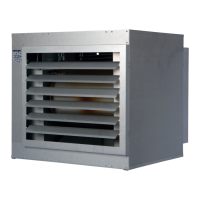
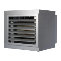
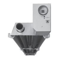
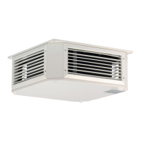
For GS+ you should use the four M10-sized suspension points [21]. GC+ devices provided with
a support frame should, when hung up, always be mounted to the support frame, see the detail in
picture [22]. Never mount to the M10-sized suspension points, as these are not intended for this
purpose. Also, remove the transport feet of the frame when the device is to be hung, see picture
[23]. Frames can be connected by means of the connection pieces as shown in picture [24].
2.2 Positioningtheuegasexhaustsystemandairsupply
The device only has the CE approval in combination with its ue gas system. The ue gas system
includes: single ue set vertical or horizontal, extension pipes and elbows. Table [4] indicates
which parts can be used per appliance type. The ue gas system must be installed according to the
instructions attached.
The extension pipes must be laid in parallel. In exceptional cases, for example with thick roofs or
walls, the roof or wall terminal may be extended concentrically by a maximum of 1 meter.
If a ue gas set is to be installed sideways to or through a ammable oor or wall, then there must
be a minimum air gap of 25 mm around the ue gas sets. This to prevent re and / or scorch hazard.
The mentioned ue gas products are made of stainless steel, or have a stainless steel inner pipe. This
has been chosen because of the maximum ue gas temperature and because of the stainless steel
heat exchanger.
The combustion air inlet pipes may consist of the same materials as specied for the ue gas
discharge, but may also consist of materials mentioned in the table on pages 7-9. Other materials are
EN