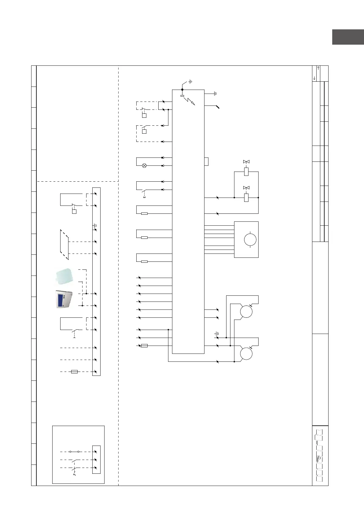
8.0 Electrical diagram GS+ 15 - 80
For G+: see inside the appliance.
EN
15
1 2 3 4 5 6 7 8 9 10 11 12 13 14 15 16 17 18 19 20
GS+ 15-80
Get.
Gec.
Electrical drawing
J.W.
TvD
Date
Norm
28-1-2022
Drawing
number
Group
Art.nr.
WLV Type
Version
WLV-012200-EN
GS+
1.1
1
c l i m a t e t e c h n o l o g y
R
Argus 864MN
Ts = 5sec
Tp = 30sec
Power supply
Digital roomtemperature sensor (optional)
Reset button
On/off switch (option)
Digital room thermostat
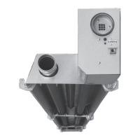
Combustion air fan
Ionization bar
Alarm light
Gasvalve
Fuse
-
-
-
-
-
-
-
-
-
TT3
S2
S1
RT
VLV
IS
H1
GV1,GV2
F1,F2
1˜ 230V / 50Hz
Isolator switchWS -
TT1
TT2
-
-
Temperatursensor in the vicinity of the unit
System / maximum temperature sensor
PE
Pressure switch filter (when used)-PF
External connections
RT TT3
Max 8 units
BUS
option
Fan motor 1VM1 -
Fan motor 2 (GS+80)-VM2
For heaters with two fans
Condensation water sensor (option)-W
optionoption
(GS+80)
*
*
1
NPE
11
L1
12
GV1 GV2
IS
T2
2
S1
01
J2-1
J2-3
J2-2
J16-7
J16-6
J5-10
J5-2
J5-12
J5-4
TT1
J5-11
J5-3
TT2.1
J13-2
J5-9
J5-1
J20-4
J20-3
J7-4
1NPEL 3 42
+
-
H1S2
13 14
J13-4
J13-3
J12
J18-2
J18-1
5 6
F2
6.3A
PE
PE
L
L1
Connection with isolator switch
1
2
WS
N
N
3
4
3 4 5 6NPEL
F1
16A
2 41 3
J5-14
J5-6
TT2.2
J13-5
J13-6
VLV
L
N
-
HALL
+
PWM
1~
M
J9-2
J9-3
J9-4
J9-5
J9-6
J9-7
PE J9-1
109
J20-2
J20-1
VM1
1~
M
VM2
1~
M
7 8
W
J16-8
J16-1
87
PF
P
W
J16-4