12
– Removal of the gas transport section provides access to the burner and the ignition/ionisation
electrode. It is recommended to replace the ignition/ionisation electrode yearly during regular
maintenance.
– Check the burner surface for irregularities. Never use a steel brush!
– Clean the gas mixer using a soft brush. Make sure that no dust gets into the burner and the gas
suction tube. Ret the gas transport section, reconnect the wiring and the gas and electrical
supplies. [27]
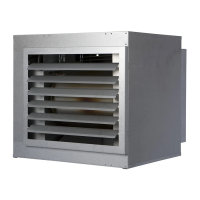
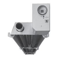
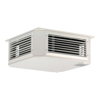
6.0 Description of parts
The parts are:
– Fan [7]
– Combustion air fan [8]
– Ignition set [9]
– Burner [11]
– Gas control unit [12]
– Ambient temperature sensor [13]
– Outlet temperature sensor / max [14]
– Gasket set [15]
– Microprocessor [16]
– Gas mixer [17]
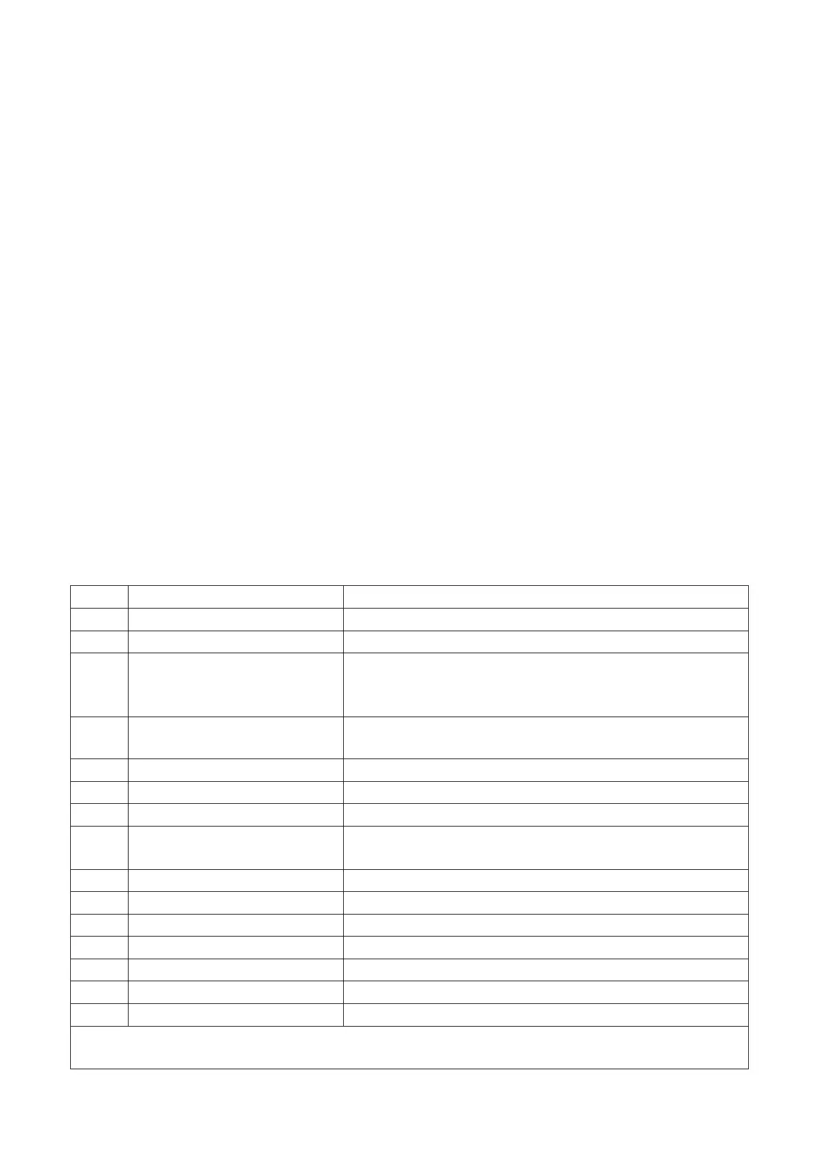
7.0 Fault codes
Code Error Description
01 Ignition failure Ignition has failed (three attempts at ignition).
02 Gas valve relay/T max. Maximum thermostat is open
03 Gas valve
Gas valve faulty / Wire connecting the gas valve to the
burner control box is open-circuit or has been incorrectly
connected.
10 Sensor diff too high
Temperature difference between both outlet temperature
sensors is too high.
25 T max. Maximum thermostat is open
31 Too many attempts to restart Flame goes out (3x) when the device is in operation.
42 Choke relay broken Relay of the choke valve is broken
43 Combustion air fan failure
The current speed of the combustion air fan deviates too
much
65 Phase and zero back to front Phase and zero not connected correctly
72 Air out sensor open Outlet temperature sensor interrupted
73 Unit temp sensor open Ambient temperature sensor interrupted
78 Air out safety open Outlet temperature sensor interrupted
80 Air out shorted Outlet temperature sensor has short circuited
81 Unit temp shorted Ambient temperature sensor has short circuited
86 Air out safety shorted Outlet temperature sensor has short circuited
When a different error code displayed on the thermostat appears, press the Reset button. If the fault
returns, please contact the vendor of the device.