5
EN
2.0 Positioning the appliance
After unpacking, check the unit for damage. Check the accuracy of the type/model, the voltage
(230 V) and the gas type. When determining the suspension height, remember to keep a sufficient
distance from any crane gantries. If necessary, shield any flammable goods. Place the appliance
and any accessories on a sufficiently solid structure, taking into account the minimum required
free space. Wall-mounting support frames are available to order. [1] [2]
INFRA / INFRA MONO
The radiant heater can be suspended with galvanised chains with links with a minimum diameter
of 4 mm and with 10 mm cross bars with good rust protection. In order to suspend the radiant
heaters in the right way, it is advisable to use eyebolts with which the radiant heaters can be
readily adjusted to the correct height. The radiant heaters can be suspended at a maximum incli-
nation of 30°. If the radiant heaters are suspended inclined, the burner is installed horizontally TO
THE LOWEST TUBE on the right, as seen from the heated area. The radiant heater must be
mounted with the flue sloping with a drop of approximately 25 mm [3].
2.1 Installing the appliance
General [4].
– Spread out the heater tubes (E) and attach them to each other using the supplied fastening
materials.
– The stainless steel burner tube (K) is for Germany
– Attach the bend * (F) to the heater tubes and, if applicable, add the retarder (J).
– Attach the suspension brackets (H) by means of straps to the correct position on the heater
tubes. Note! The first strap from the burner should not be fastened, to allow for expansion.
– Attach the reflectors to the suspension brackets.
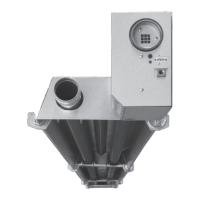
– Next, the burner (A) and, if applicable, the flue fan (B) can be mounted.
– Once all the components have been mounted, the whole radiant heater assembly can be
suspended.
• Fastening point for reflector
* if applicable.
2.2 Positioning the flue and combustion air supply.
Position the system and attach it in the correct manner in accordance with the gas flue installa-
tion instructions. Ensure that there is a good and tight connection to the appliance. To absorb
expansion differences, a flexible part should be included in the supply line.
The appliance only has CE approval if the roof or wall pass-through supplied by the manufacturer
is used. This may be supplied by the manufacturer under the following part numbers:
Device type Roof pass-through Wall pass-through
13 59 90 556 59 90 579
22 59 90 556 59 90 579
38 59 90 560 59 90 583
50 59 90 560 59 90 583