7
Normal Use
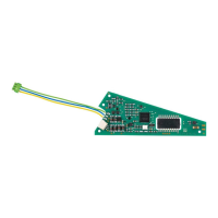
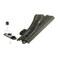
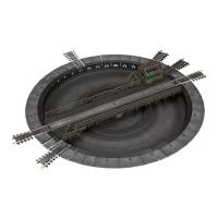
• This digital installation decoder is designed for installation in
Märklin and Trix C Track turnouts with a turnout mechanism
(exception: Märklin three-way turnout).
• This digital installation decoder may only be connected to
Märklin or Trix switched mode power packs for external
power supply.
• This decoder may only be used in dry areas indoors.
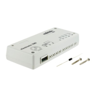
Contents as Delivered
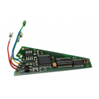
1 digital installation decoder
1 cable – yellow, red, and brown (for Märklin C Track)
1 cable – blue, red, and white (for Trix C Track)
Installation instructions
Warranty card
Additional tools required for installation: tweezers and soldering
station for a maximum soldering temperature of 30 watts /
300˚ Celsius / 572˚ Fahrenheit with a fine point, Electronic solder
(0.5-1 mm dia.), desoldering braid or desoldering pump.
Safety Notes
• IMPORTANT! This product has sharp edges and points related
to its function.
• Do wiring and assembly work only in a voltage-free work
environment. Otherwise you may experience electrical current
dangerous to the body leading to injury.
• Operate this decoder only with the permissible voltage
(see technical information).
When using a solder station there is the danger of burning
your skin.
Important Information
• Important: When installing the digital installation decoder,
try to avoid touching components on the upper side of the
decoder. Static charge can affect the function of the decoder.
• The operating instructions are a component part of the
product and must therefore be kept with the product,
particularly when it is given to another party.
• For repairs please see your authorized Märklin specialty
dealer.
• http://www.maerklin.com/en/imprint.html
Technical Data
• Load at lantern output ≤ 100 milliamps
• Load at turnout output max. 2 amps
• Voltage for the digital power circuit max. 20 volts eff.
• External voltage max. 20 volts DC
• Electrical strength max. 40 volts
Functions
• Capable of multi-protocols: fx (MM), mfx* and DCC
• Setting the mode of operation by means of DIP switches, see
Page 38
• Addresses can be set with DIP switches:
1-256 fx (MM) (Control Unit 6021 / Central Station 1)
1-320 fx (MM) (Central Station 2/3 / Mobile Station 2)
1-511 (DCC)
• Programmable addresses using CVs
1-2,044 DCC
• The last respective address setting is valid, regardless of
whether it was done with programming or with the DIP
* mfx not until CS 2 Software Version 4.0