6
Safety Notes
• Thismodelmayonlybeusedwiththeoperatingsystem
designed for it.
• Useonlyswitchedmodepowersupplyunitsandtransfor-
mers that are designed for your local power system.
• Thislocomotivemustneverbesuppliedwithpowerfrom
more than one power pack.
• Paycloseattentiontothesafetynotesintheinstructions
for your operating system.
• Notforchildrenundertheageof15.
• WARNING! Sharp edges and points required for operation.
Important Notes
• Theoperatinginstructionsareacomponentpartofthe
product and must therefore be kept in a safe place as
well as included with the product, if the latter is given to
someone else.
• PleaseseeyourauthorizedLGBdealerforrepairsor
spare parts.
• http://www.maerklin.com/en/imprint.html
Functions
• ThismodelisdesignedforoperationonLGBtwo-railDC
systems with conventional LGB DC train controllers or
power packs (DC, 0 - 24 volts).
• InterfaceforinstallationofDCC.
Note:Usealocomotivecontrollerwithmorethan1ampof
train current for this model.
This model is equipped with standard LGB couplers on the
front and rear.
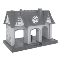
Mode of Operation Switch
This model has a four-way power control switch underneath
the roof segment of the cab (Fig. 1), which can be easily
removedmanually:
Pos. 0 All power off
Pos. 1 Power to lights generator
Pos. 2 Power to motors and lights
Pos. 3 Same as Position 2
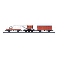
Multi-Purpose Socket
There are multi-purpose sockets suitable for flat connectors
on the front walls (Fig. 2). This socket can be used to provide
track power to LGB cars with lighting or sound electronics.
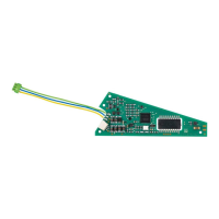
Multi-Train System
The model is equipped with a digital interface to connect a
3 amp DCC decoder (Fig. 3). Remove the plug on the decoder
interface and connect the decoder.
We recommend to use MTS Decoer III, the plug of which di-
rectly fits into the socket interface. We recommend to have
the decoder mounted by the LGB factory service station.
When a decoder is integrated in the locomotive, the power
control switch ist obsolete.