12
Wiring
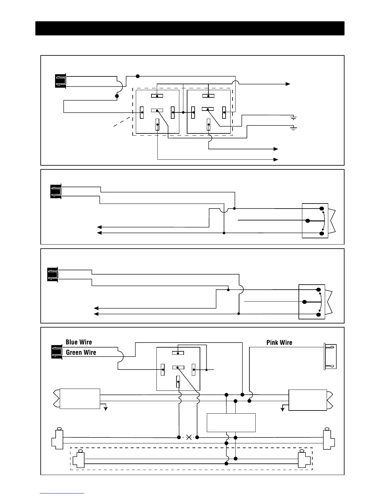
Harness 5: 3-Pin Mini Black Connector
(continued)
Unlock Driver's Door First for 3-Wire Negative Door Lock Systems
87
87A
85
86
30
Unlock Wire
Passenger's Door
Lock
Unlock
To +12V or Ground
To +12V or Ground
Driver's Door
Rear Doors
Passenger's
Door Switch
Door Lock Relay
Control Module
Lock
Unlock
+12V
ALA984H
Relay
Driver's Door
Switch
Cut
Connector
White 5-Pin
Mini Connector
3 Wire Ground Trigger Door Lock System
(
-
) Lock Out
Ground Input
(
-
) Unlock Out
To Door Lock
Control Relays
Lock Control
Switch
Blue Wire: Connect to Unlock
Green Wire: Connect to Lock
Black 3-Pin
Mini Connector
3 Wire Positive Trigger Door Lock System
(+) Lock Out
+12 Volts Input
(+) Unlock Out
To Door Lock
Control Relays
Blue Wire: Connect to Lock
Green Wire: Connect to Unlock
Lock Control
Switch
Black 3-Pin
Mini Connector
Newly Installed Power Door Lock Motors
87
87A
85
86
30
87
87A
85
86
30
To +12 Volts
(Battery +)
To Ground
To Newly
Installed Power
Door Lock Motors
White Wire
Brown Wire
Green Wire: Lock
Blue Wire: Unlock
Violet Wire
ALA-DL1
Relay Pack
Red Wire: Lock
Black Wire: Unlock
Black 3-Pin Connector
Green Wire
Blue Wire
Note: Orange wire from ALA-DL1
must be connected to +12V
M7A-IM 6/22/06 4:53 PM Page 12
 Loading...