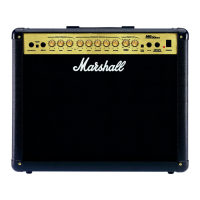
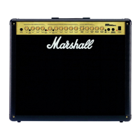
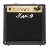
Do you have a question about the Marshall Amplification MG GOLD SERIES and is the answer not in the manual?
Details about mains input voltage, fuse value, and correct fuse fitting. Avoid bypassing or using incorrect fuses.
Safety guidelines for moving the amplifier, ensuring it's switched off and unplugged with cables disconnected.
Ensures correct impedance, speaker cable usage, and proper connection sequence for safe operation.
Device compliance with FCC Rules Part 15 and Canadian ICES-3(B)/NMB-3(B) standards.
Description of the input jack for guitar and the gain control for signal and distortion.
Controls for switching between Clean/Crunch and OD-1/OD-2 channels.
Bass, Middle, and Treble controls to adjust the overall tone and depth.
Controls for adjusting reverb amount and selecting/adjusting digital effects.
Controls for the delay effect, including delay time and tempo setting.
Master volume control and the Damping switch for power amp response.
Description of Headphone/Line Out, Store, and Power switches.
Details on the power input, voltage rating, and fuse location.
Jack socket for connecting the optional footcontroller.
Socket for connecting internal or external speakers, detailing impedance requirements.
Socket for connecting external audio sources like MP3/CD players for practice.
Sockets for connecting external effects processors to the series FX loop.
Explanation of how to select between the four amplifier channels (Clean, Crunch, OD1, OD2).
Describes the two operating modes: Preset mode (stored settings) and Manual mode (physical controls).
Details how settings are stored and recalled within each channel preset.
Explains that amp settings always match the physical position of controls in this mode.
Overview of the amplifier's simultaneous digital effects including reverb, delay, and FX types.
Instructions on connecting external audio sources for practice sessions.
How to use the 3.5mm socket for headphones or as a line out signal.
Explains the Damping switch's role in altering power amp response and feel.
Details on how the series FX loop works with guitar or professional rack effects units.
Crucial warning to use only non-screened Marshall approved speaker leads.
Information on speaker sockets for MG101FX/MG101FX and MG100HFX models.
Explanation of the power switch function for turning the amplifier on and off.
Procedure to reset the amplifier and footswitch to their original factory default settings.
Methods for assigning specific front panel switches to footswitches.
How the digital display indicates functions, status, and recalled presets.
Explanation of what the LED status panel indicates about the amplifier or tuner.
Default footswitch assignments and general programming capabilities.
Procedures for storing front panel switches or complete presets to footswitches.
How to overwrite or store altered channel or footswitch presets.
How the digital display indicates recalled presets and altered settings.
Methods to access the tuner and how it indicates tuning status.
| Type | Solid State |
|---|---|
| Channels | 2 |
| Effects | Reverb, Chorus, Delay |
| Controls | Gain, Volume, Bass, Middle, Treble, Reverb |
| EQ Controls | Bass, Middle, Treble |
| Outputs | 1 x 3.5mm Headphone |
| Footswitch | Optional |


