6 CONNECTING TO AN AMPLIFIER
Connections are made via stripped wires to avoid the need for soldered
connectors. The EM15 is provided with two spring-loaded terminals on the
rear of the enclosure and the EM150 is provided with two pairs of 4mm
screw terminals – a pair for each 10"(250mm) driver.
For mono EM150 operation these should be connected together externally
in parallel: left Red (+) to right Red (+), left Black (-) to right Black (-). The
paralleled mono impedance is 4 ohms. For stereo operation, separate
connections should be made to the EM150’s left and right terminals. The
impedance in this case is 8 ohms left and 8 ohms right.
Note: It is important to maintain consistent polarity throughout i.e. Red to
Red, Black to Black.
7 SYSTEM CONFIGURATIONS
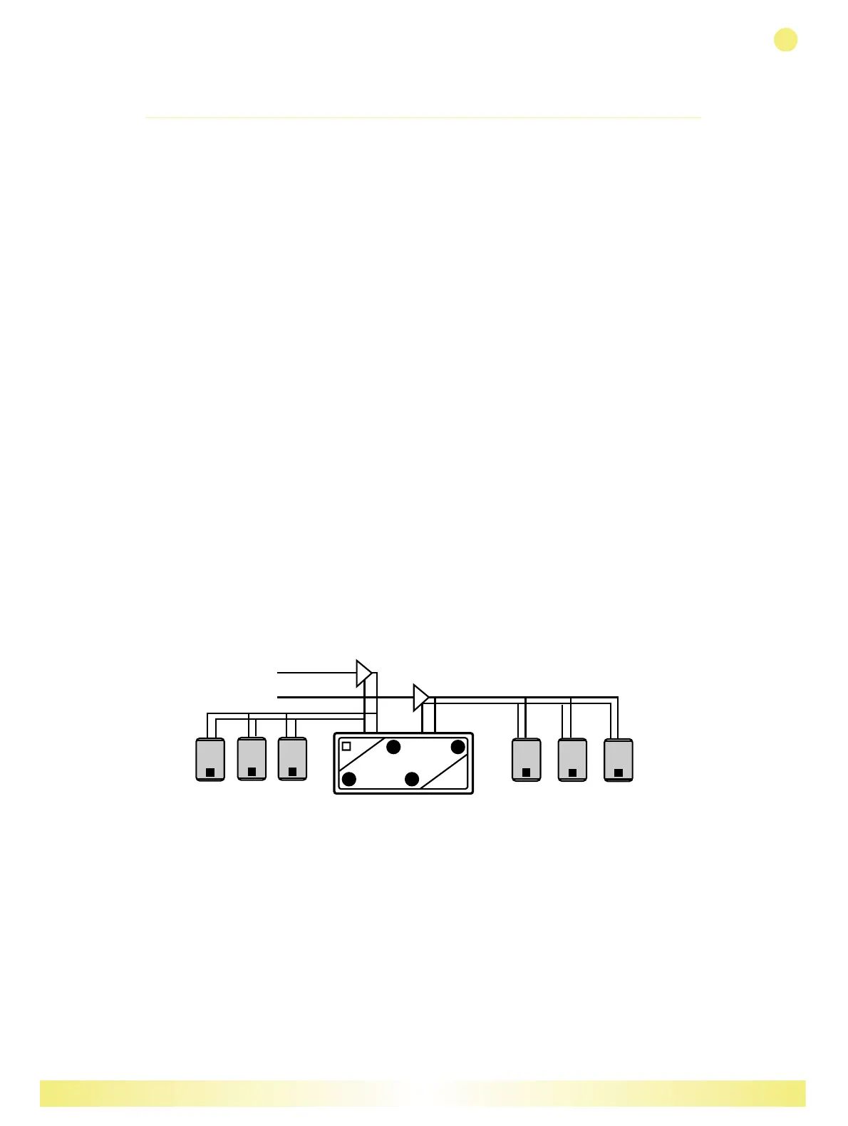
The basic system configuration for one EM150 and up to six EM15’s is
shown in Fig 2. Up to three EM15’s (each in 16 ohm configuration) are
wired in parallel with the respective left and right inputs of the EM150, and
driven from the left and right channels of the power amplifier. This
arrangement presents a 3 ohm load to each amplifier channel. Alternatively,
one EM150 may be used with a pair of EM26’s, presenting a 4 ohm load to
the amplifier.
Fig 2
Martin Audio – EM SERIES
ENGLISH
5
 Loading...