20 5
1.2 Earth Continuity
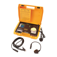
For this test a voltage of 6V AC is applied between the earth pin of the plug of the
appliance and its exposed metalwork, via the wander earth lead. The resulting
high current verifies that the protective earth path will carry fault currents in the
event of a breakdown within the appliance.
Alternatively, the 100mA soft test can be selected for testing IT equipment. For
this test, a constant current of 100mA DC is applied between the earth pin on the
plug of the appliance and its exposed metalwork via the earth wander lead.
1.3 Fuse Rating
A low AC voltage is applied between the phase and neutral of the appliance to
ensure that excessive currents will not flow when the full mains supply is used
during a run test. This test is displayed but not recorded.
Note that a ruptured fuse will pass this test, since it cannot supply excessive
currents. A ruptured fuse should have been found during preliminary visual tests,
or will be revealed during the run test.
1.4 Insulation
500V DC is applied between the appliance phase and neutral joined together and
earth to ensure that the insulation has not fallen below an acceptable level.
1.5 Run (Load)
This is an optional test that may be omitted. The appliance under test is operated
at the nominal mains voltage. Care should be taken to ensure that there is no
mechanical hazard with this test.
1.6 Earth Leakage
During the run test, current flow in the earth lead and wander earth lead is
monitored to check that no potentially hazardous, voltage induced, earth leakage
paths are created by the operating conditions.
1.7 Flash
This is an optional test that may be omitted. On Class I appliances 1.5kV AC is
applied between the phase and neutral joined together and earth. The flash probe
is not required for Class I appliances. However, on Class II appliances, 3kV AC is
applied between the phase and neutral joined together and the tip of the flash
probe which is touched onto any exposed appliance metalwork. This test is a
further verification that functional and supplementary insulation levels have not
deteriorated.
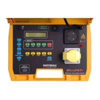
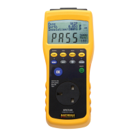
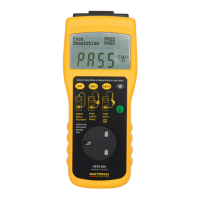
The tester can be run in either a manual or an automatic mode. Manual mode
allows any or all tests to be performed in any sequence as desired. In the
automatic mode tests are performed in a prescribed sequence. Pass/fail values
are preset and the test results are displayed on a high contrast LCD.
pressing the CLASS key. When the PROCEED key is pressed, if a Class I test is
specified, the display indicates the continuity test parameters. Pressing the
PROCEED key initiates the AUTO TEST.
3.4.3 Appliance and User I.D.
It is possible to enter appliance I.D.’s from the keyboard, or from bar codes using
a bar code reader connected to the serial port. The user I.D. is entered via the
keyboard. However, the keyboard is numeric, 0-9, and in order to enter letters,
the following procedure must be followed. Press the SET UP key and then press
the numeric keys over the range, 00-27. The character conversion table on the lid
label indicates the two digit codes required for each letter of the alphabet.
3.4.4 PROCEED and MAN Keys
These are the two most used keys on the keyboard. The PROCEED key is similar
to the enter key on a PC. It accepts entries and increments the sequences. The
MAN key is essentially the clear key, returning the PAT to its READY mode.
However, in certain circumstances, it acts as a skip key, allowing certain tests to
be skipped or ignored.
3.5 110/240V Operation
The PAT has the option of carrying out any of the above tests with either 110V or
220/240V mains. This instrument can be connected directly to a 220/240V supply
using the 13A plug fitted on the supply lead or to a 110V supply using the
supplied adaptor. On power up, the PAT will monitor the mains supply and adjust
its measurement circuits and select the correct test socket accordingly. The
display will also indicate the supply voltage on which tests will be carried out.
Appliances to be tested should be connected into the appropriate socket and be
compatible to the supply currently in use with the PAT. i.e. 110V appliance - 110V
supply.
Fig. 11
3.6 Battery Backup
During times that no mains power is connected to the PAT, a battery ensures that
the records stored in memory are maintained. The expected life for this battery
will be approximately five years depending on use.
READY DATE 15/02/02
USING 240V MAINS
 Loading...