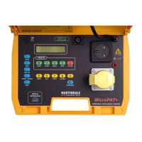
18 7
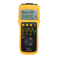
INSULATION TEST
Test Voltage: 500VDC -0%, + 20% at 0.5MΩ
Short Circuit Current: 1.5mA DC nominal
Pass Level: >1MΩ Class I There is no distinction between
>2MΩ Class II As New or In Service pass levels
Range: 0 - 19.9MΩ
Accuracy of Indication: ±5% ±1 digit of reading
RUN TEST
Range: 0 - 3.1kVA
Pass Level: <3.1kVA at 240V AC/<1.43kVA at 110V AC
Accuracy of Indication: ±10% ±100VA at nominal 240V mains supply
±10% ±50VA at nominal 110V mains supply
EARTH LEAKAGE TEST
Range: 0 - 6mA AC
Pass Level: <3.5mA AC Class I, 0.5mA AC Class II
Accuracy of Indication: ±10% ±1 digit of reading
FLASH TEST
Test Voltage: 1.5kV AC - Class I at nominal
3.0kV AC - Class II 240V mains supply
Pass Level: <3mA AC
Range: 0 - 3mA AC.
Accuracy of Indication: ±5% ±1 digit
LEADS
Mains: 1.7m fixed lead, with a 13A moulded plug
Earth Continuity: 1.5m long, fixed lead, heavy duty crocodile clip
Flash Test: 1.3m long, detachable, with a retractable probe at one
end and a shrouded free 4mm safety high voltage plug
at the other.
Adaptor: 110V 16A plug at one end and a 240V 13A free socket
at the other.
SOCKETS
Mains: 240V 13A to BS1363
110V 16A to BS4343
and then the user I.D. will appear as already described. The prompt to enter the
test code will now be displayed. A number obtained from the “Table of Codes for
Test Parameters” should now be entered via the keyboard or from a bar code
reader connected to the serial port. Once the correct test code is displayed, then
the PROCEED key should be pressed to continue with the test. Once the correct
type of test has been set on the display operate the PROCEED key to continue
with the test.
If a Class I type test has been selected the display will then identify the type of
continuity test and the continuity pass limit. On pressing the PROCEED key, the
display will change to prompt for the earth wander.
The wander earth should then be carefully attached to any exposed metalwork on
the appliance and the PROCEED key pressed to start the test.
The display will indicate that the continuity test is running and after five seconds it
will momentarily show the test result.
If the result of this test is within the pass limit, the display will then change to
indicate that the fuse test is running and will then move on to the insulation test.
This test will run for 5 seconds, during which time the insulation of the appliance
is stressed with 500V DC and the insulation resistance is measured.
If the continuity or insulation test fails, the rest of the test sequence is
discontinued and when the PROCEED key is pressed, the prompt for saving the
test results will appear on the display.
If Class II double insulated appliance test is selected then the continuity test is
omitted. The display will prompt for the wander earth to be fitted to any exposed
metalwork on the appliance to ensure that the insulation test will be valid.
If there is no exposed metalwork on the appliance, metal foil should be wrapped
around the appliance and the wander lead clip attached to the foil.
Press PROCEED to start the fuse test. The display will indicate that the fuse test
is running and after five seconds it will momentarily show the test result and move
onto the insulation test. This test will run for five seconds, during which time the
insulation resistance is measured.
If the insulation test fails, the rest of the test sequence is discontinued, and when
the PROCEED key is pressed, the prompt for saving the test results will appear
on the display.
}
{
 Loading...