CONNECTION
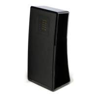
These
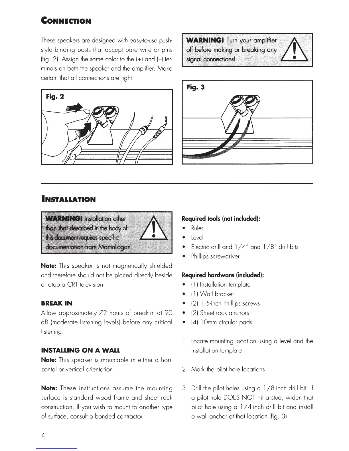
speakers are designed with easy-to-use
push-
style
binding
posts that
accept
bare
wire
or pins
(fig. 2). Assign
the
same color to the(+) and (-)
ter-
minals on both
the
speaker and
the
amplifier.
Make
certain that all connections are tight.
Fig. 2
INSTALLATION
Note:
This speaker
is
not
magnetically
shielded
and therefore should not be placed directly beside
or
atop
a
CRT
television
BREAK
IN
Allow
approximately
72
hours
of
break-in at
90
dB (moderate listening levels) before
any
critical
listening.
INSTALLING
ON
A WALL
Note:
This speaker
is
mountable
in
either a hori·
zontal or vertical orientation
Note:
These instructions assume the
mounting
surface
is
standard
wood
frame
and
sheet rock
construction.
If
you wish to mount to another type
of
surface, consult a bonded contractor
4
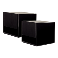
Fig. 3
Required
tools
(not
included):
•
Ruler
•
Level
• Electric drill and 1 I
4"
and 1
/8"
drill bits
• Phillips screwdriver
Required
hardware
(included):
• (
1)
Installation template
• ( 1 )
Wall
bracket
•
(2)
1 .5-inch Phillips screws
•
(2)
Sheet rock anchors
•
(4)
l
Omm
circular pads
Locate mounting location using a level and
the
installation template.
2
Mark
the
pilot hole locations
3 Drill the pilot holes using a 1
/8-inch
drill bit.
If
a pilot hole DOES
NOT
hit a stud,
widen
that
pilot hole using a 1 / 4-inch drill bit and install
a wall anchor at that location (fig.
3)
 Loading...