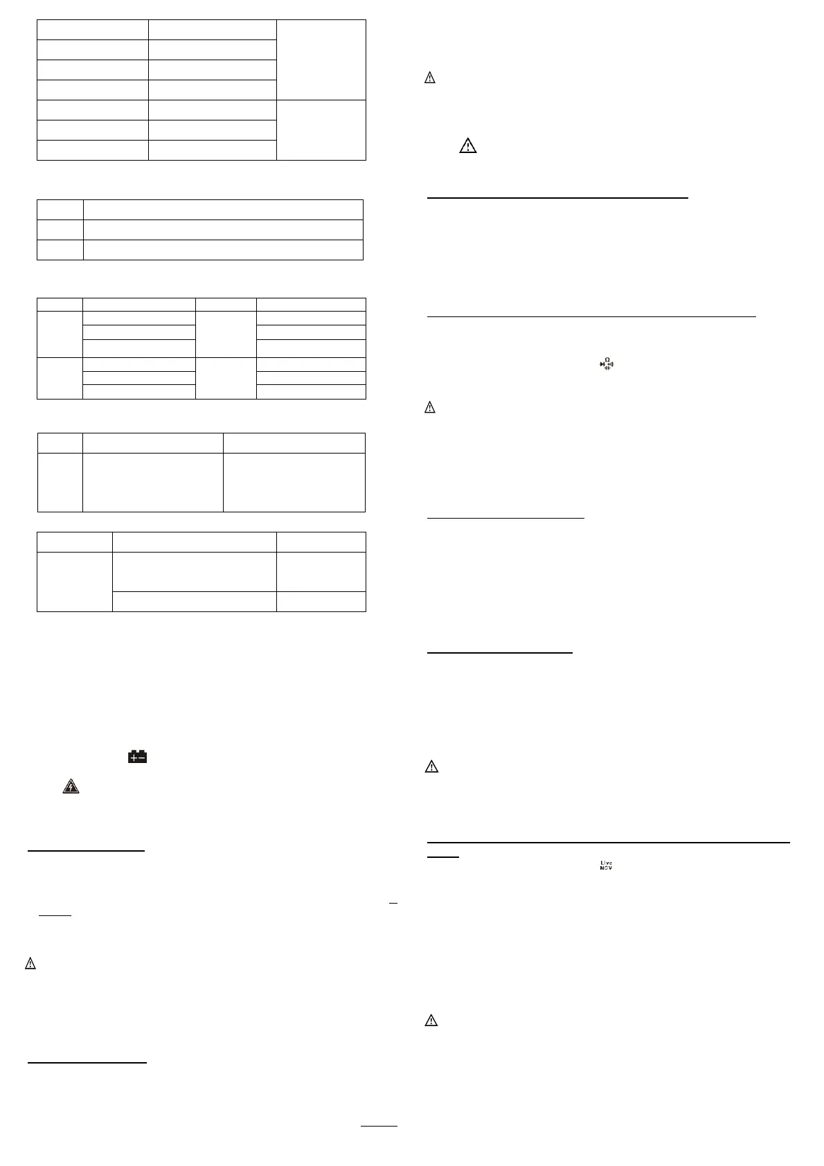
Overload protection: 250V DC or AC RMS
Non-Contact AC Voltage Detection (NCV): Measures AC voltage >30V-1000V/50Hz-60Hz.
Live Wire Identification (Live): Measures AC voltage >90V-250V/50Hz-60Hz.
Operation Instructions
Precautions before Operation:
Operating Instructions
Precautions before Operation:
1. Power on the instrument and check if it has sufficient battery. If the battery
voltage is low, the symbol will appear on the display, indicating that the
battery needs to be replaced before use.
2. The symbol next to the test lead input jack indicates that the input voltage
or current must not exceed the specified value to protect the internal circuitry
from damage.
3. Before testing, the function/range dial should be set to the desired range.
Voltage Measurement
1. Insert the red test lead into the VΩmA jack. Insert the black test lead into the
COM jack.
2. Set the function/range dial to the DCV or ACV voltage position. Use the test
leads to measure the voltage of the circuit being tested (connect the test leads in
parallel with the circuit).
3. Read the measured voltage value from the LCD.
4. When in the ACV voltage position, pressing the SEL button will switch the
device to frequency measurement mode.
Note:
⚫ The maximum input voltage for the voltage range is 600V RMS. To avoid risk
of electric shock or instrument damage, do not attempt to measure voltage
higher than 600V RMS.
⚫ In the 600mV range, the instrument may show a reading even without any input
or connection to the test leads. This is normal and does not affect the accuracy of
the measurements.
Current Measurement
1. Insert the black test lead into the COM jack. If the current to be measured is less
than 600mA, insert the red test lead into the VΩmA jack; if the current is
between 600mA and 10A, insert the red test lead into the 10A jack.
2. Set the function/range dial to the Current position, then press the SEL button to
select “DCA” or “ACA” measurement mode, and connect the test leads in series
with the load to be tested. The current value and the polarity of the red test lead
will be displayed simultaneously.
3. Pressing the SEL button will also display the frequency of the measured current.
Note:
● If the current range to be measured is unknown, set the function dial to the
highest range and gradually reduce it until satisfactory resolution is achieved.
● If the display shows only “OL”, it indicates an overload, and the function dial
must be set to a higher range.
● The symbol next to the test lead input jacks indicates a maximum input
current of either 600mA or 10A, depending on the jack being used. Excessive
current will blow the fuse.
Frequency and Duty Cycle (Hz/%) Measurement
1. Insert the black test lead into the COM jack. Insert the red test lead into the
VΩmA jack.
2. Connect the test leads to both ends of the signal source being measured. Read
the measured value from the LCD.
3. Press the SEL button to switch between frequency (Hz) and duty cycle (%)
modes.
Diode, Capacitance, Resistance, and Continuity Measurement
1. Insert the black test lead into the COM jack. Insert the red test lead into the
VΩmA jack.
2. At this point, the red test lead will have a positive (+) polarity.
3. Set the function/range dial to the position, then press the SEL button to
select the desired measurement mode. Connect the test leads to the circuit (red to
“+”, black to “-”). Read the measured value from the LCD.
Note:
⚫ When there is no input, e.g., when there is an open circuit, the instrument will
display “OL” for diodes, resistance, and continuity, and “0000” for capacitance.
⚫ Before measuring resistance in a live circuit, ensure that all power sources are
turned off and all capacitors are fully discharged.
During continuity testing, if resistance is less than approximately 50Ω ± 30Ω,
the built-in buzzer will sound, indicating continuity between two points
Transistor hFE Measurement
1. Set the function/range dial to the hFE position and properly insert the transistor
test accessory.
2. Determine whether the transistor is NPN or PNP type, then insert the E, B, and
C terminals of the transistor into the corresponding sockets of the test accessory.
3. The instrument will display the approximate hFE value. The test conditions are a
base current of approximately 10uA and a Vce of approximately 2.8V.
Temperature Measurement
1. Turn the function/range dial to the ℃/℉ position. At this time, the LCD will
display the ambient temperature of the instrument. Press the SEL button to
switch between ℃ and ℉ measurement modes.
2. When using a thermocouple for temperature measurement, insert the red plug
of the K-type thermocouple into the ℃℉ jack and the black plug into the
COM jack. Use the thermocouple probe to contact the object or area to be
measured.
3. Read the temperature of the object being measured from the LCD.
Note: The instrument uses a cold-junction compensation circuit located inside the
front end of the instrument. Due to the instrument's good sealing, it takes time to
reach thermal equilibrium with the measuring environment. Therefore, the
instrument should be placed in the measuring environment for an extended
period to obtain more accurate readings.
Non-Contact Voltage Detection (NCV) and Live Wire Identification
(Live)
1. Set the function/range dial to the position, then press the SEL button to
select “NCV” or “Live” measurement mode. The LCD will display “EF” (for
NCV mode) or “LIVE” (for Live mode).
2. Insert the red test lead into the VΩmA jack.
3. Move the NCV detection area at the top of the instrument (or the tip of the red
test lead) close to the live object. If voltage is detected, the NCV indicator light
will flash, and at the same time, the buzzer will emit a “beep-beep-beep” alarm
sound to warn the user that voltage is present in the area.
4. While in “Live” mode, use the tip of the red test lead to touch the AC voltage.
When the instrument emits a “beep-beep-beep” alarm sound, the NCV indicator
light flashes, and the LCD displays “LIVE”, the wire being touched is the live
wire.
Note:
⚫ Even if there is no indication, voltage may still be present. Do not rely solely on
the NCV detector to determine whether a conductor is live.
⚫ Detection results may be affected by factors such as socket design, insulation
thickness, and material type.
⚫ External sources of interference (e.g., flashlights, motors, etc.) may affect the
instrument, causing inaccurate detection.
⚫ If the circuit has severe leakage, the meter may also emit a warning sound when
the red test lead touches the neutral wire.
 Loading...