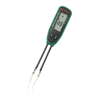
The Smart SMD Tester, model MS8910, is a handheld, battery-operated tool designed for convenient measurement of Surface Mounting Devices (SMD) such as chip resistors, capacitors, and diodes. It also features continuity checking. The device automatically identifies passive components, allowing for fully automatic detection and measurement.
Function Description:
The MS8910 is primarily used for:
- Resistance Measurement: Capable of measuring resistance from 300 Ω up to 30 MΩ.
- Capacitance Measurement: Measures capacitance from 3 nF up to 30 mF.
- Diode Check: Performs diode testing with an open voltage of 2.8V and a testing current of 2mA.
- Continuity Check: Indicates continuity with a 2KHz beep when resistance is less than 30 Ω.
- Scanning Mode: Automatically identifies the type of component (resistor, capacitor, diode) and continuity, then enters the corresponding measurement mode.
- Data Hold: Allows users to freeze the current measurement on the LCD.
Important Technical Specifications:
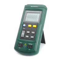
- Display: 3000 count LCD display.
- Measurement Modes: Full automatic measurement with auto-scanning for Resistance, Capacitance, and Diode. Manual function selection via the "FUNC" push button.
- Overload Indication: Displays 'OL' when the measurement exceeds the range.
- Low Battery Indication: Alerts the user when the battery needs replacement.
- Power Supply: 1x 3V Lithium Battery (CR2032).
- Test Pins: Gold-plated to reduce contact resistance and prevent rust.
- Auto Power OFF: Automatically turns off after 10 minutes of inactivity to conserve battery life.
- Operating Temperature & Humidity: 0 ~ 40°C (32 ~ 104 °F) & < 80% RH.
- Storage Temperature & Humidity: -10 ~ 50°C (14 ~ 122 °F) & < 70% RH.
- Safety Class: IEC1010-1, CAT II.
- EMC: Conforms to CE regulation 89/336.
- Dimensions & Weight: 170 x 31 x 17mm, approximately 48.6 g.
- Environmental Conditions: Suitable for indoor use, altitude up to 2000 meters.
Electrical Specifications (Accuracy):
- Resistance:
- 300 Ω / 3 KΩ / 30 KΩ / 300 KΩ / 3 MΩ: ±(1%rdg + 2dgt) with 0.1 Ω resolution.
- 30 MΩ: ±(1.2%rdg + 3dgt).
- Capacitance:
- 3 nF / 30 nF / 300 nF / 3 uF / 30 uF / 300 uF / 3 mF / 30 mF: ±(2%rdg + 3dgt) with 1 pF resolution.
- 300 uF / 3 mF / 30 mF: ±(3%rdg + 3dgt).
Usage Features:
- Power On/Off: The Tester powers on immediately upon battery installation. It does not have a dedicated power key. Auto power-off activates after 10 minutes of idle time. Pushing any button can turn the Tester on again after auto power-off.
- "FUNC" Button: This button acts as a function selector, allowing users to switch between Resistance, Capacitance, Diode, and Continuity measurement modes manually. In auto-scanning mode, the 'SCAN' and '----' signs are displayed on the LCD.
- "HOLD" Button: Pressing this button enters or exits the data hold mode, stopping LCD updates and displaying the stored measurement data.
- LCD Display Indicators:
- 'SCAN': Indicates auto scanning mode.
- 'AUTO': Indicates auto ranging.
- 'H': Indicates data hold.
- Diode symbol: Indicates diode checking mode.
- Continuity symbol: Indicates continuity checking mode.
- 'numF': Capacitance units (nF, uF, mF).
- 'MK Ω': Resistance units (Ω, KΩ, MΩ).
- Battery symbol: Low battery indicator.
- Safety Precautions:
- Always inspect the Tester case, pin holder, and gold-plated pins before use. Do not use if damaged.
- Do not use the Tester as tweezers to prevent pin tip damage.
- Never apply external voltage between the two pins.
- Avoid using the Tester in environments with explosive gas, vapor, or dust.
- Crucially, never use the Tester on live circuits.
- When measuring SMD devices on a PCB, always disconnect power and discharge all high-voltage capacitors to prevent damage to the meter or the equipment under test.
- Diode Check Operation:
- Use the diode test mode to check diodes, transistors, and other semiconductor devices.
- A good silicon junction typically shows a voltage drop between 0.5V and 0.8V.
- For forward voltage drop, touch the 'INPUT' terminal pin to the component anode and the other pin to the component cathode.
- If the diode is good, the display shows "OL" when the pins are reversed.
- If the diode is shorted, the display shows 0 (zero) in both directions.
- If the diode is open, the display shows "OL" in both directions.
- Continuity Check Operation:
- The buzzer sounds a 2KHz beep when the resistance reading is less than 30 Ω.
Maintenance Features:
- Replacing the Battery:
- When the low battery indicator is displayed, the battery must be replaced to maintain normal operation.
- Open the battery cover on the bottom case using a screwdriver.
- Remove the old battery and snap a new 3V CR2032 Lithium Battery into the holder.
- Cleaning:
- The meter can be cleaned with a soft, clean cloth to remove oil, grease, or grime.
- Do not use liquid solvent or detergent.
The Tester's outer surface is made with thermo plastic elastomer, and the gold-plated testing pins ensure reduced contact resistance and prevent rust, enhancing the device's durability and reliability. The manual emphasizes careful reading of safety and caution information to ensure proper and safe operation.