8
ASSEMBLY INSTRUCTIONS
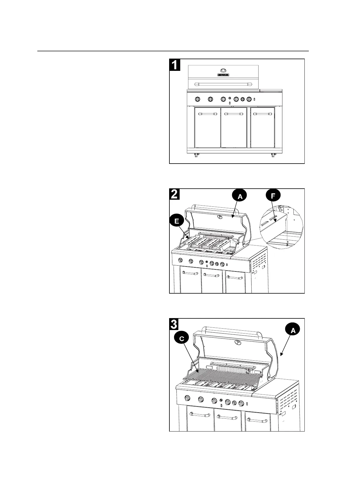
1. Remove all the packing material
from inside and outside gill.
2. Place all three flame tamer 1s (E)
and the flame tamer 2 (F) on top of each
burner on the main bod (A). F l ame
tamer 2 (F) should be placed on top of
the far right burner.
3. Place the grids (C) on the main body
(A) as shown.
,16758&7,216'¶$66(0%/$*(
1. Retirer tout le matériel d’emballage à
O¶LQWpULHXUHWjO¶H[WpULHXUGXJULO
3ODFHUOHVWURLVGLIIXVHXUVGHÀDPPH
(HWOHGLIIXVHXUGHÀDPPH)VXU
chaque brûleur du module principal (A). Le
GLIIXVHXUGHÀDPPH)GRLWrWUHSODFp
sur le brûleur le plus à droite.
3. Placer les grilles (C) sur le module prin-
cipal (A) tel qu’illustré.
46