8
ASSEMBLY INSTRUCTIONS
8
D
FF
E
FF
FF
FF
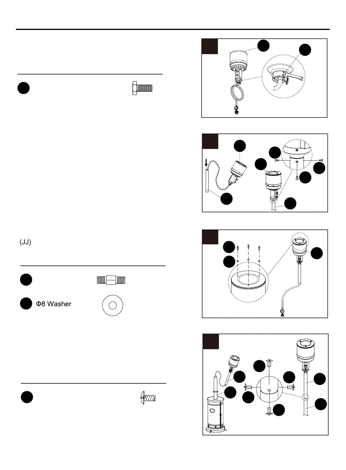
8. Insert hose of head assembly into post 2 (E). Secure
post 1 (D) assembly to post 2 (E) with screws (FF).
Note: The control knob on head assembly should
be above the decal on pole.
Hardware Used
FF
x 4
M3/16in Screw
E
D
GG
GG
x 4
Stainless Steel Bolt
5. Unscrew stainless steel bolts (GG) from head
assembly (C).
Hardware Used
6. Insert hose of head assembly into Secure
head assembly to with stainless steel bolts (GG).
Note: The control knob on head assembly should be
above the decal on pole.
5
6
C
D
GG
GG
GG
C
GG
D
C
7
JJ
EE
C
7. Attach reflector spacers (EE) and Ø8 washers
reflector spacers
(EE)
EE
JJ
x 3
Reflector Spacer
x 3
Hardware Used
to the top of head assembly (C). Tighten the
post1 (D)
post1 (D)