or PVC tail piece with a nut. Repeat the procedure for the outlet
connection.
DO NOT OVERTIGHTEN THE NUT.
Figure 2
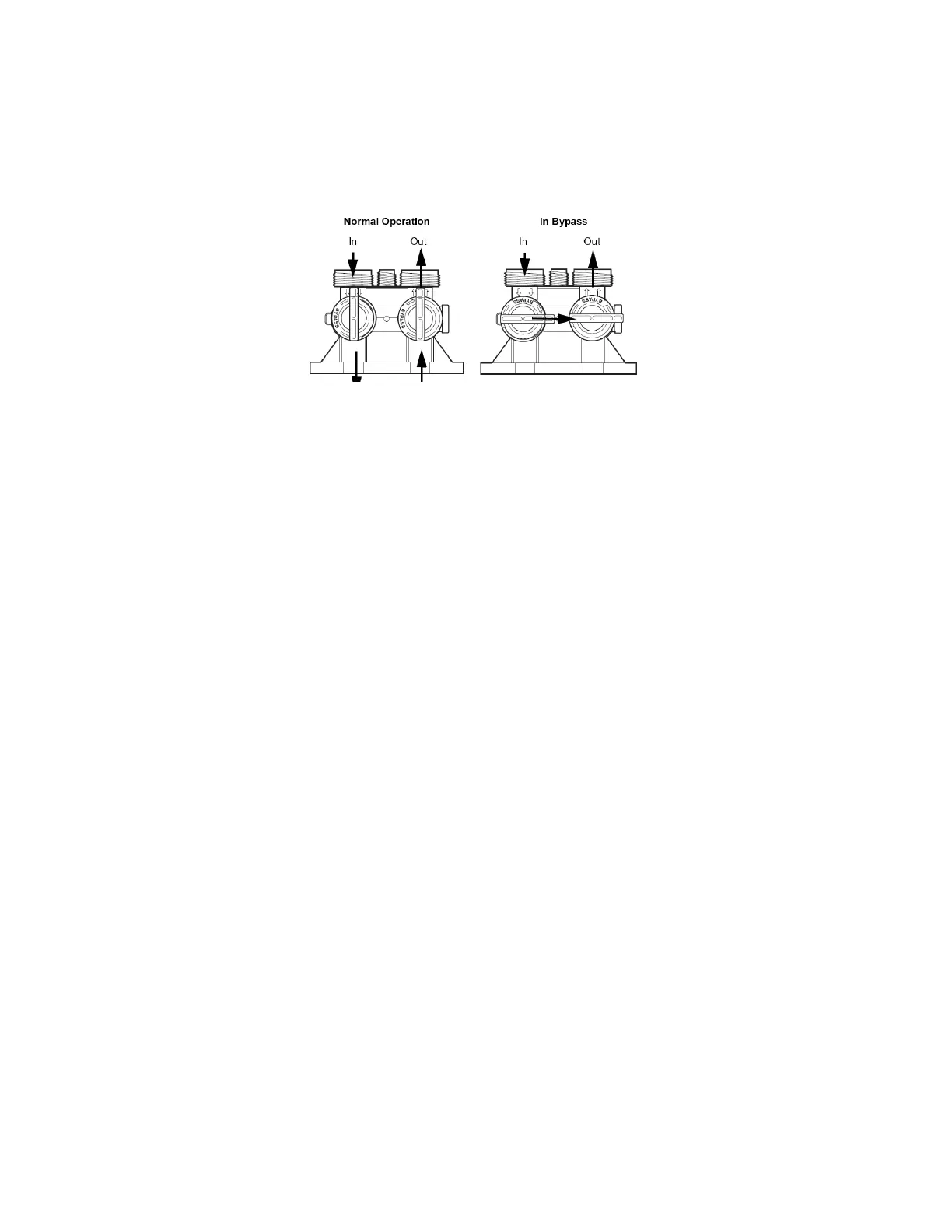
2. The control valve's drain connection is 1/2" npt and is located on
the back of the bypass valve.
3. Turn the control valve upside down and ensure that the control
valve distributor o'rings are in place. Use silicone lubricant on the
o'rings.
4. Fill mineral tank with water before installing control valve.
5. Place the control valve onto the distributor pipe.
6. Thread the control valve hand tight to 20 foot pounds!
DO NOT OVERTIGHTEN!
**DO NOT USE PETROLEUM!**
**USE ONLY SILICONE **
Service and Drain Piping:
1. Pipe Filter into the service lines .The inlet and outlet connections
of the control valve are 3/4” copper or PVC and are located on
the back of the valve body. As you face the timer the inlet is on
the left and the outlet is on the right. Always follow local
plumbing codes when installing our water treatment equipment.
2. If sweat fittings are used, be sure soldering is done in such a
manner as not to allow heat to reach the control valve or bypass.
(If Schedule 80 PVC is used make sure to follow the proper
primer and solvent instructions.)
3. The drain line connection is located on the back of the bypass
valve as you face the timer. It is recommended you install a 1/2”
union on the drain line for servicing. The drain line must be of
adequate size to allow for full regeneration flow.


 To Next Page