Installation 4
BEFORE YOU INSTALL YOUR PUMP
NOTICE: Well must not be more than 20' (6.1m) depth to
water.
Step 1. Long runs and many fittings increase friction and
reduce flow. Locate pump as close to well as pos-
sible; use as few elbows and fittings as possible.
Be sure suction line is straight and angles toward
pump.
Step 2. Be sure well and pipe are clear of sand, dirt and
scale. Foreign matter will plug pump and void
warranty. Use new pipe for best results.
Step 3. Protect pump and all piping from freezing.
Freezing will split pipe, damage pump and void
warranty. Check locally for frost protection
requirements (usually pipe must be 12" (30.5cm)
below frost line and pump must be insulated).
Step 4. Be sure all pipes and foot valve are clean and in
good shape.
Step 5. No air pockets in suction pipe.
Step 6. No leaks in suction pipe. Use Teflon tape or
Plasto-Joint Stik to seal pipe joints.
Step 7. Unions installed near pump and well will aid in
servicing. Leave room to use wrenches.
Pump body may explode if used as booster
pump. DO NOT use in booster application.
Motor normally operates at high tempera-
ture and will be too hot to touch. It is pro-
tected from heat damage during operation by an auto-
matic internal cutoff switch. Before handling pump or
motor, stop motor and allow it to cool for 20 minutes.
CASED WELL/DUG WELL INSTALLATION
Step 1. Inspect foot valve to be sure it works freely.
Inspect strainer to be sure it is clean and secure.
Step 2. Connect foot valve and strainer to first length
of suction pipe and lower pipe into well. Add
sections of pipe as needed, using Teflon tape on
male threads.
Use 1-1/2” pipe for 1 and 1-1/2 HP pumps. Use 2”
pipe for 2 HP pumps.
Be sure all suction pipe is leakproof or pump will
lose prime and fail to pump. Install foot valve 10 to
20 ft. (3 to 6 m) below lowest level to which water
will drop while pump is operating (pumping water
level). Your well driller can furnish this informa-
tion.
Step 3. To prevent sand and sediment from entering
pumping system, foot valve/strainer should be at
least 5 ft. (1.5 m) above bottom of well.
Step 4. When proper depth is reached, install sanitary
well seal over pipe and in well casing. Tighten
bolts to seal casing.
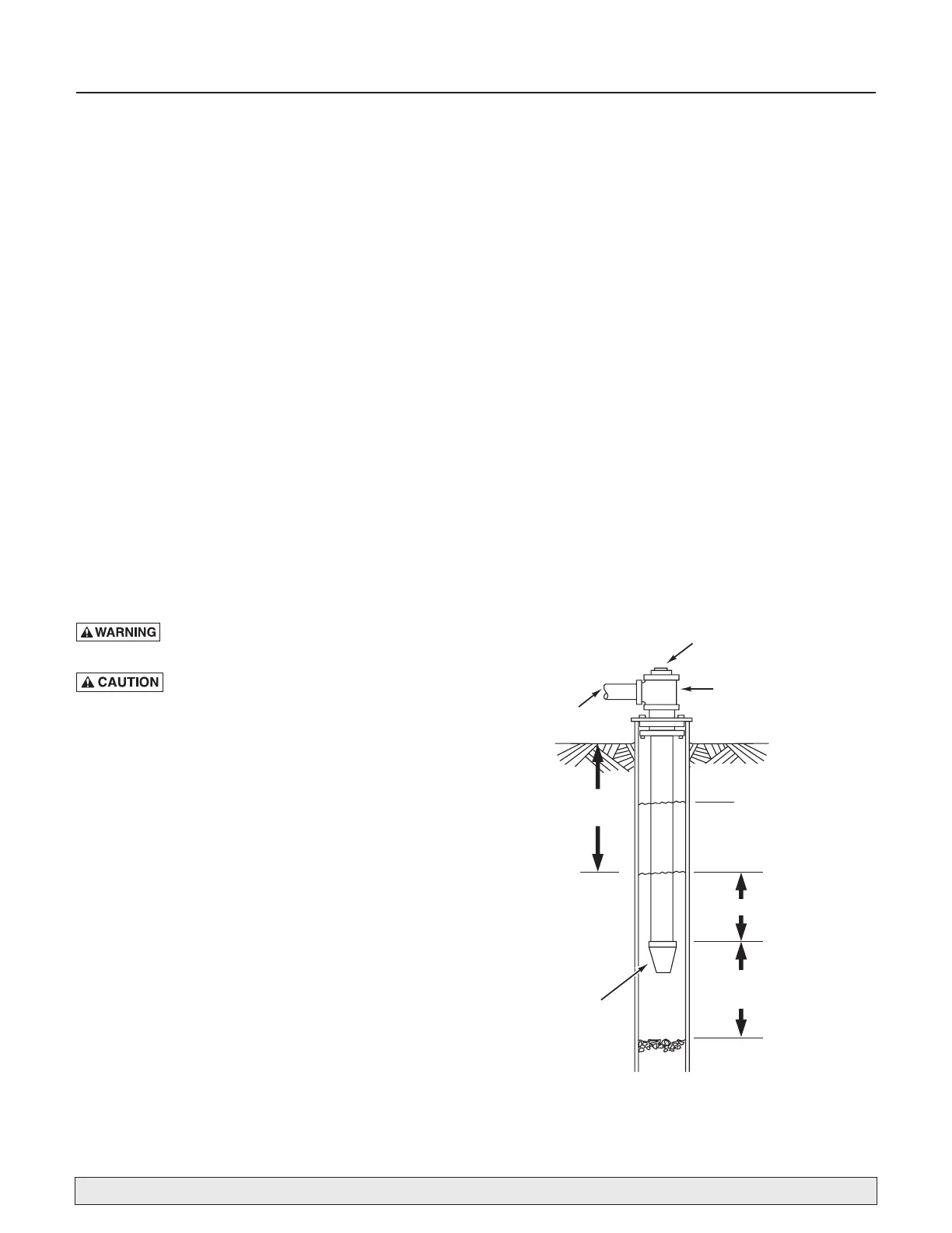
Step 5. When using foot valve, a priming tee and plug are
recommended. (Figure 1).
Suction
pipe
Foot
Valve
Priming plug
Priming tee
Drawdown water
level (pump on)
10-20' (3-6 m)
20' (6 m)
max.
At least 5 feet
(1.5 m)
Standing water
level (pump off)
For parts or assistance, call Master Plumber Customer Service at 1-800-628-9439
Figure 1: Cased/Dug Well Installation