Do you have a question about the Master B150 and is the answer not in the manual?
Important safety warnings and precautions for operating the heater.
Warning about the life-threatening risk of carbon monoxide poisoning.
Explains signs of carbon monoxide poisoning and who is most affected.
Lists essential safety rules for fuel, ventilation, clearances, and operation.
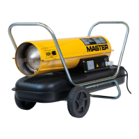
Diagram showing the components of the 30/70,000 BTU/Hr heater models.
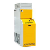
Diagram showing the components of the 90,000 BTU/Hr heater model.
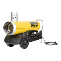
Diagram showing the components of the 150,000 BTU/Hr heater model.
Lists the necessary tools for assembling the heater.
Illustrates the assembly process for wheels and handles on specific models.
Describes how fuel is drawn from the tank and sprayed into the combustion chamber.
Explains how the fan moves air to heat and provide a stream of hot air.
Details how the electronic ignitor and spark plug start the heater.
Explains the function of the flame-out control system for safety shutdown.
Crucial warning about using only kerosene or paraffin, not flammable fuels.
Advice on using clean containers and avoiding foreign matter in fuel.
Specifies the minimum fresh air opening requirements for safe operation.
Details the color code for wiring the 13-amp plug for the power cord.
Step-by-step instructions for starting the heater safely.
Provides guidance on selecting the correct wire size for extension cords.
Instructions on how to properly shut down and restart the heater.
Detailed steps for draining and storing the heater for the off-season.
Important advice against storing old fuel for future use due to potential damage.
Schedule for maintenance tasks like fuel tank flushing and filter cleaning.
Reinforces the warning against servicing a hot or plugged-in heater.
Diagnoses causes and remedies for the heater shutting off shortly after ignition.
Diagnoses causes and remedies for the heater failing to ignite while the motor runs.
Diagnoses causes and remedies for the motor not starting or rotating slowly.
Instructions for safely removing the upper shell of the heater.
Procedure for removing and servicing the fuel filter on 30/70,000 BTU/Hr models.
Procedure for removing and servicing the fuel filter on the 90,000 BTU/Hr model.
Procedure for removing and servicing the fuel filter on the 150,000 BTU/Hr model.
Procedure for removing, cleaning, and regapping the spark plug for the 30,000 BTU/Hr model.
Illustration showing the correct spark plug gap specification and adjustment.
Diagram illustrating the correct rotation for positioning spark plug electrodes.
Procedure for removing, cleaning, and regapping the spark plug for 70/90/150,000 BTU/Hr models.
Diagram showing spark plug removal for 70/90/150,000 BTU/Hr models.
Illustration of the spark plug gap for 70/90/150,000 BTU/Hr models.
Steps for removing, cleaning, or replacing air output, intake, and lint filters.
Important instruction not to oil the filters.
Steps to adjust and check the pump pressure using a gauge.
Diagram illustrating the pump pressure adjustment process and specifications.
Procedure for removing and cleaning the nozzle for the 30,000 BTU/Hr model.
Diagram illustrating the removal of the nozzle assembly.
Procedure for removing and cleaning the nozzle for 70/90,000 BTU/Hr models.
Diagram showing the removal of the burner head.
Procedure for removing and cleaning the nozzle for the 150,000 BTU/Hr model.
Diagram showing the removal of the burner head for the 150,000 BTU/Hr model.
Steps to address a binding pump rotor, including cleaning and gap adjustment.
Diagrams showing the location of the rotor assembly in different models.
Illustration of the gap adjusting screw locations on the rotor.
Diagram showing the method for lightly sanding the rotor.
Instructions for removing and reinstalling the fan from the motor shaft.
Diagrams showing the fan, motor shaft, and setscrew.
Provides technical specifications for the heater models, including output, fuel, and electrical requirements.
Details the terms and conditions of the 90-day limited warranty.
Information on how to communicate with the factory for warranty service.