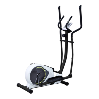
EN
FIG.1
ASSEMBLY INSTRUCTION:
1.PREPARATION:
A. Before assembling make sure that you will have enough space around the item.
B. Use the present tooling for assembling.
C. Before assembling please check whether all needed parts are available (at the above
of this instruction sheet you will find an explosion drawing with all single parts (marked
with numbers) which this item consists of.
2.ASSEMBLY INSTRUCTION:
:
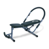
FIG.2
FI G.2:
First, the elastic bolt (7) of the large ball
head is relaxed and pulled down, then the
seat cushion adjusting pipe assembly
(10) is inserted into the inter-tube bushing
of the main frame assembly (16) to make
it in an appropriate position, then the
elastic bolt (7) of the large ball head is
released and locked. At the same time,
the cushion sliding pipe assembly (12) is
inserted into the cushion regulating pipe
assembly (10), and the cushion is locked
by the cushion locking torsion (23) and
the gasket (22). Finally, the cushion (13)
is locked with a tool (with a cross
wrench).
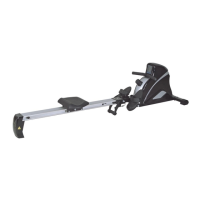
FIG.1:
Attach the Front Stabilizer (pt.15) to
the Main Frame (pt.16) using two sets of
Ø8 Flat Washers (pt.5), M8 Domed Nut
(pt.6) and M8*52 Carriage bolt (3).
Attach the Rear Stabilizer (pt.4) to the
Main Frame (pt.16) using two sets of Ø8
Flat Washers (pt.5), M8 Domed Nut (pt.6)
and M8*52 Carriage bolt (3).
The aluminium alloy kettle frame (19)
and the screw (86) are fixed on the main
frame (16) with a cross screwdriver.