4
2. Insert short yellow hose into the “plastic bottle with two openings” which is supplied. Carefully attach the short
yellow hose to the oil drain fitting on the recovery machine. As hose is tightened on fitting, oil will flow into container.
(Hose is equipped with a depressor which will open core valve in oil drain fitting).
3. When oil has drained completely, disconnect the hose from the system. Unscrew the cap/hose from the bottle and
dispose of the oil into an environmentally approved container.
MAINTENANCE REQUIREMENTS
1. Replace filter if sight glass indicator is red/orange in color. The color change may be green/blue for dry condition when
refrigerant is passing through and red/orange in color for wet condition.
2. Replace filter after recovering refrigerant from a known contaminated system.
3. Replace filter if excessive pressure drop is indicated. Difference of pressure gauge reading before and after filter.
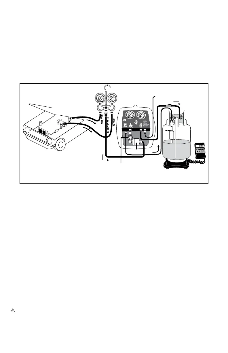
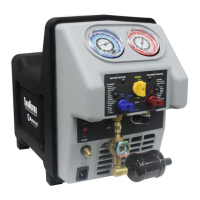
LIQUID
SUCTION PRESSURE DISCHARGE PRESSURE
PURGE
PURGE (START)
INLET
POWER
CIRCUIT
BREAKER
OUTLET
CLOSE
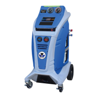
Recovery
System
DO NOT fill tank more
then 80% of capacity!
Approved
Recovery
Tank
Figure 2
Float Switch
Cable
BLUE
YELLOW
RED
Oil Drain Port
80%
YELLOW
Low Side
High Side
Inlet Filter
Sightglass
Moisture
Indicator
To connect yellow hose from
manifold to the recovery, use
provided adapter.
Connections for liquid/vapor recovery using manifold gauge set
69100-INST-UNIV
For parts or service contact the service department: 1-888-825-6989
WARNING: This product can expose you to chemicals including lead and lead compounds, which are known to the
State of California to cause cancer and birth defects or other reproductive harm. For more information go to
www.P65Warnings.ca.gov