3www.mastercool.com
CAUTION: This equipment should be serviced by authorized personnel only to maintain flammability rating.
WARNING: There is the possibility of refrigerant and equipment contamination from hydrocarbons or leak
sealants in the refrigerant container or the mobile A/C system being serviced or refrigerant container.
NOTE: Use only new refrigerant oil to replace the amount removed during the recycling process. Used oil should
be discarded per applicable federal, state, and local requirements.
The manufacturer shall not be responsible for any additional costs associated with a product failure including,
but not limited to, loss of work time, loss of refrigerant, cross contamination of refrigerant, and unauthorized
shipping and/or labor charges.
IMPORTANT: R1234yf systems have special fittings (per SAE specifications) to avoid cross-contamination with
R134a systems. DO NOT adapt your unit for a different refrigerant — system failure will result.
PERIODICALLY INSPECT AND MAINTAIN REFRIGERANT HOSES AND SEALS TO ENSURE THAT HOSES AND SEALS
PREVENT THE ADDITION OF EXCESS AIR, DUE TO LEAKS, DURING THE RECOVERY PROCESS, WHICH WOULD
INCREASE THE NCG LEVEL IN THE RECOVERED REFRIGERANT AND COULD MAKE AN EXPLOSIVE MIXTURE WITH
HYDROCARBON REFRIGERANTS.
All hoses used for interconnecting system should have shut off valves (manual or automatic) on both ends. Treat all hoses
and connections with caution. Hoses or connections will contain liquid refrigerant or gas under pressure. Connect and
disconnect fittings with caution.
The Recovery System includes a fine screen filter at the inlet port. Screen should be checked often or whenever contami-
nation prevents proper operation of recovery system.
SPECIFICATIONS:
• Rated Voltage: 120 V
• Frequency: 60 HZ
• Full Load Amperage: 7.6A
• Locked Rotor Amperage: 25.2 A
• Output: 1/2 HP
• Class: A
• Continuous Duty
• Design Pressure: 400 psi outlet, 175 psi inlet
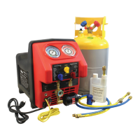
OPERATING GUIDE FOR DIRECT VAPOR OR LIQUID RECOVERY (Refer to fig.1)
Note: A. If recovery machine shuts off due to full tank, close valve on tank and shut off machine. Replace and connect
empty recovery tank to yellow hose and restart Recovery Machine.
1. Make sure on-off switch is off, “O” pushed in. Connect system to grounded power connection.
2. Turn INLET (blue color) valve to CLOSE position. Turn center valve (yellow color) to RECOVER position.
3. Connect blue hose from low side system connection to inlet port.
4. Connect yellow hose from outlet port of recovery machine to vapor (gas) connection on recovery tank.
5. Connect float switch cable from recovery machine to recovery tank.
NOTE: Recovery system will not operate if float switch cable is not connected. Recovery tank must be
Mastercool part #62011-LH and have a maximum capacity switch to prevent over filling of tank. Purge
air and moisture from system by bleeding lines or use a vacuum pump.
6. Open the vapor valve on the recovery tank.
7. Turn OUTLET (red color) valve to OPEN position.
8. Turn INLET valve on Recovery System to OPEN.
9. Observe operation of system. In rare instances “slugging” may be apparent (loud compressor noise or high vibration).
If this condition is apparent turn inlet valve to LIQUID position. System can be run with this setting continuously. It is
suggested that operator periodically turn inlet valve to OPEN position and check for proper operation of system. Best
operation of the system is with inlet valve OPEN and automatic pressure regulating valve controlling flow conditions.
10. When the inlet pressure is 15” Hg or more, the recovery is done. To purge the Recovery System, leave the system
running. Turn the center valve to PURGE. Turn the inlet valve to PURGE. It may take 1 or 2 minutes to purge the
Recovery machine of refrigerant, depending on how much liquid is in it.
11. Make sure the Recovery system is off. Turn the inlet and outlet valves to CLOSE. Close the valve on the tank and
remove the hoses.
 Loading...