2
Av. Carr. Miguel Alemán #6061, Col. América, Cd. Guadalupe, Nuevo León, México, C.P. 67130
www.Impco.com.mx (81)-8144-5440
AP059719 2/2008
1450 E. Grant Street, Phoenix, Arizona U.S.A.
www.AdobeAir.com 602-257-0060
LOCATION
ASSEMBLY INSTRUCTIONS
TOOLS REQUIRED
• 3/8
˝
Open End Wrench
•
3/8
˝
B
ox End Wrench
• 6
˝
Adjustable Wrench
• 7/16
˝
Box End Wrench
• #2 Phillips Screwdriver
Picture 1
Picture 2
Picture 3
F
igure 1
Figure 2
Figure 3
Figure 4
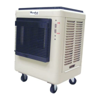
Always make sure the unit is operated on a level surface. The
best location for it is near a partially opened window or door
where hot outdoor air can be drawn into the unit. This cooler is
portable, but use caution when rolling the unit to avoid splash-
ing and spilling of water. Cool air can best be directed through
the space by using a partly opened window or door
, ideally one
that is situated on the opposite side of the
space from the cooler. This allows the cooled air to be moved
through the space and exhausted back outdoors which is
critical to proper performance of the cooler.
!
Figure 5
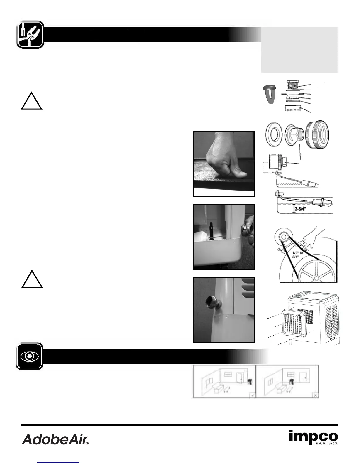
Check Belt Tension.
This applies only to models
with belt drive construction.
Check belt tension (Figure 4)
by pushing downward on it.
proper tension will allow
deflection 1/2˝ to 3/4˝. To
adjust belt tension, loosen
bolt in slot of motor support
bracket, adjust to proper
tension and retighten bolt.
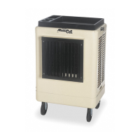
Unpacking the Mobile MasterCool
®
.
The unit is shipped with the
molded plastic tray not attached. Remove the plastic tray from the carton and
then remove the cooler from the carton.
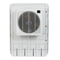
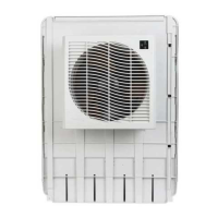
Grille Installation.
Before attempting to use your new Mobile MasterCool
cooler you must complete the grille installation.
CAUTION: Handle the grille with care it may have
sharp edges or burrs.
Using the four Phillips screws and lock washers (included) start each screw
into each path, then tighten for assembly of the grill to the front of the cabinet.
DO NOT OVER TIGHTEN. See Figure 5
Installing the casters.
Some models ship with the wheels already
attached to the cabinet bottom. If wheels are not attached then locate the
wheels inside of the cooler and attach them to the cabinet bottom using the
bolts included.
Attaching the plastic tray.
Remove the side pad frames from the cooler
by lifting them up and out of the cooler cabinet. Locate the parts bag in the
cooler and attach the tray top using the push rivets provided. (Picture 1)
Installing the drain bushing and plug.
If it is not already installed, refer
to Figure 1 and install the drain bushing and cap through the hole
provided in the bottom of the cooler.
Installing the float valve and adapter.
Refer to Figure 2 and attach the
float to the side leg of the cooler using the hole provided. The garden hose
adapter attaches to the brass inlet fitting on the float valve. Verify that the hose
washers are properly in place. (Picture 2)
Connecting to Water
.
Move the cooler to an area where it can be filled
with water and drained. The cooler should be located on level ground.
Connect to a water supply using a commercial grade garden hose (supplied by
customer) connected to the adapter on the float valve and turn on the water.
Verify water tight connections by visually examining both the float / hose con-
nection and the drain plug. (Picture 2)
CAUTION: Water inlet pressure should be limited to a
maximum of 105 PSI or an inline pressure regulator
should be installed.
Adjusting the water level.
Refer to Figure 3 and set the water height as
shown by adjusting the float.
Connecting to a Power Supply
.
Plug the gro
unde
d plug directly into a
120 Volt AC 60 Hz grounded GFCI protected electrical power sup
ply.
Note:
Improper voltage will burn out the motor and pump windings and will
void the warranty.
!
Push Rivet
H
ose Adapter
D
rain Bushing
W
asher
Cooler Bottom
Lock Nut
Washer Inside
Cap
Cap
 Loading...