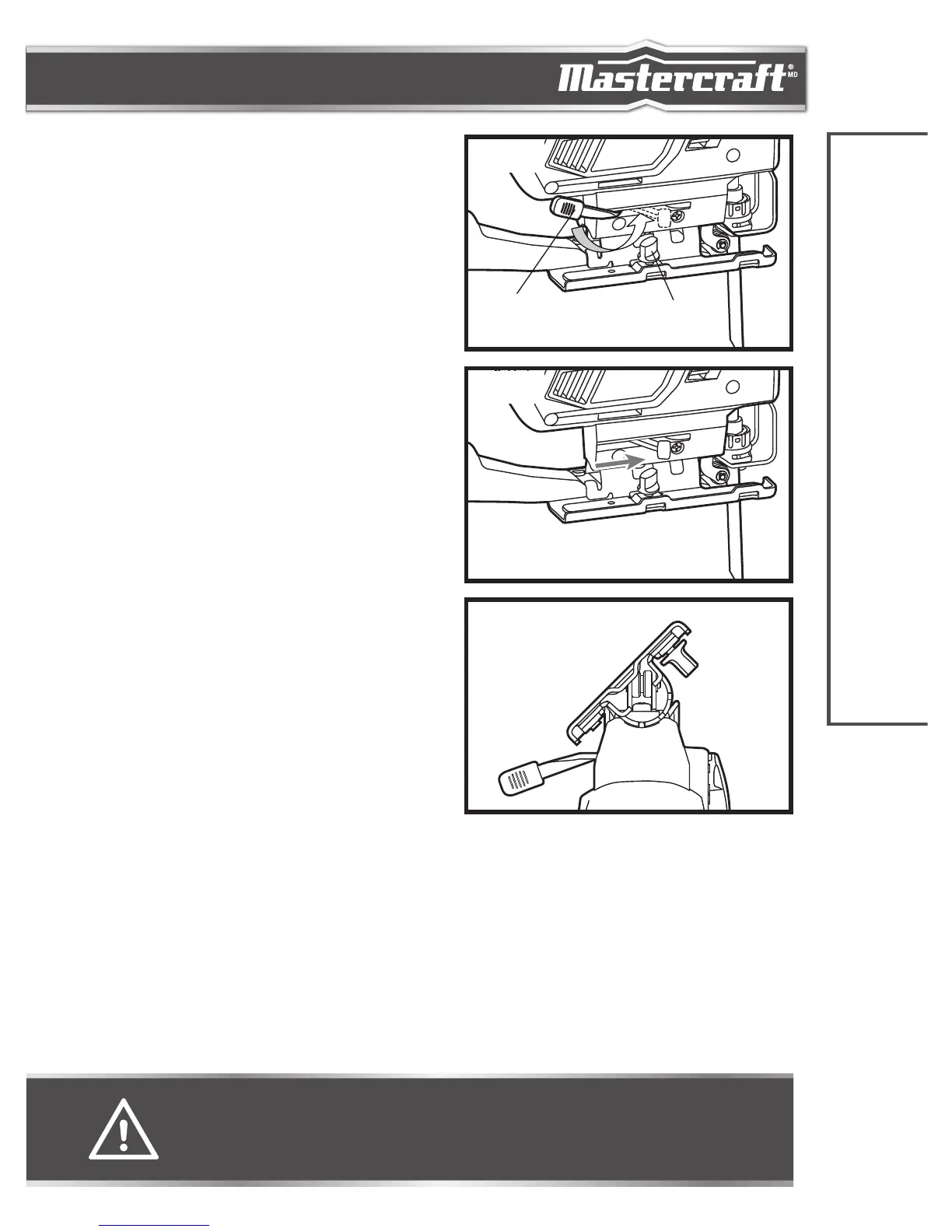
ADJUSTING THE BASE PLATE FOR BEVEL
CUTTING
(fig 3a, 3b & 3c)
1. Rotate the keyless bevel lever to unlock the base plate;
refer to fig 3a.
2. When the adjustment is blocked by the locking knob on
the plate base, change it to another side.
3. Move the base plate forward so that the base plate can
be beveled; refer to fig 3b.
4. The base plate can be beveled to the left or to the right
and has detents at 0° and 45°; refer to fig 3c. The base
plate can be manually stopped between 0° and 45°
according to the scale marked on the base bracket.
5. When the desired bevel angle is achieved, move the
base plate backward; rotate the keyless bevel lever
back to lock the base plate.
6. Accurate work requires a trial cut. Measure the work
after cutting and reset the angle as necessary setting
until the correct setting is achieved.
ASSEMBLY INSTRUCTIONS
WARNING!
• Do not use a dust extraction system or a vacuum cleaner when cutting metal. Sparks may ignite residual
wood dust.