headline bars
continuation tabs
notes
warnings
headline bars
continuation tabs
notes
warnings
headline bars
continuation tabs
notes
warnings
13
headline bars
continuation tabs
notes
warnings
headline bars
continuation tabs
notes
warnings
headline bars
continuation tabs
notes
warnings
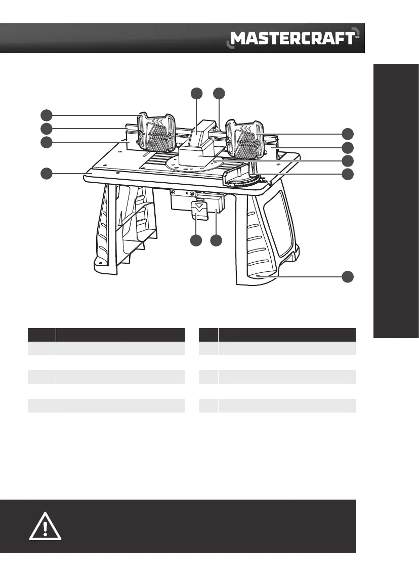
KEY PARTS DIAGRAM
4
3
2
1
8
9
10
4
7
5 6
1112
No. Description No. Description
1 Tabletop surface 7 Fastening holes
2 Out-feed fence 8 Mitre-gauge
3 Extended fence 9 Above-table height adjust hole
4 Feather board 10 In-feed fence
5 Integrated safety switch 11 Vacuum adaptor
6 Switch box 12 Dust collection and guard
The router table has a precision-built electric switch box, and it should only be connected to a 120V
AC, 60Hz power supply (normal household current). DO NOT operate on direct current (DC). The large
voltage drop would cause a loss of power, and the motor would overheat. If the router table does not
operate when plugged into correct 120V AC, 60Hz outlet ONLY, check the power supply. The router table
comes with a 6’ (1.8m) power cord (no adaptor needed).
KEY PARTS DIAGRAM
WARNING!
• Do not allow familiarity with the router table to cause a lack of alertness. A fraction of a second of carelessness
is enough to cause severe injury.
 Loading...