NOTE:
The safety key (3) can be removed from the switch when it is in the Off position. With the key removed, the
switch is locked in that position and the lathe cannot be started. Store the key in a safe place when the lathe
is left idle (Fig. 8).
Fig. 5
Fig. 6
Fig. 7
Fig. 8
WARNING!
Do not operate the lathe until it is completely assembled and adjusted according to the instructions.
CAUTION!
Never leave the lathe unattended until it has come to a complete stop.
WARNING!
If the motor shuts off unexpectedly, unplug the lathe from the power source, make sure the On/Off
switch is in the Off position, and allow the motor to cool down before attempting to restart the
lathe. Overheating may be caused by misaligned parts or a dull chisel. Inspect the lathe for proper
set-up before using it again.
model no. 055-4504-8 | contact us 1-800-689-9928
19
OPERATING INSTRUCTIONS
18
ASSEMBLY INSTRUCTIONS
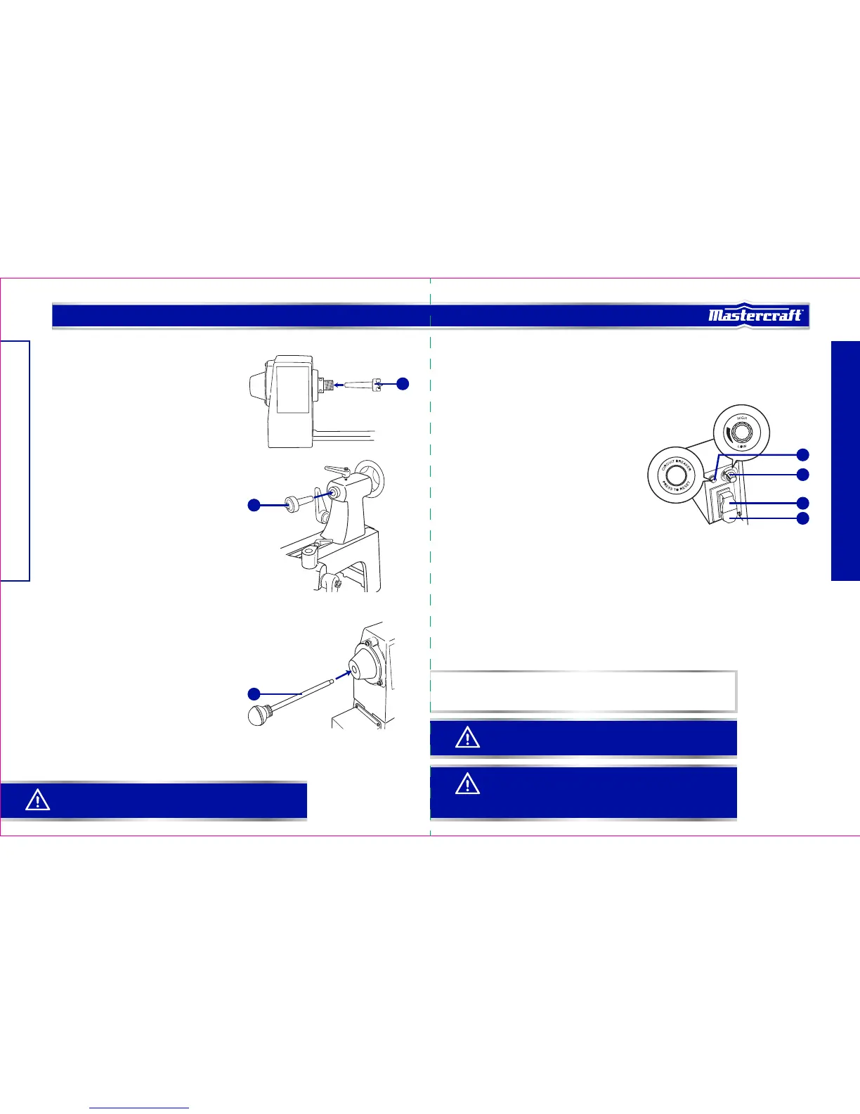
INSTALLING SPUR AND CENTRE (Figs. 5-6)
• Insert the shaft of the headstock spur centre (1) into the
hollow centre of the headstock spindle (Fig. 5).
• Insert the shaft of the tailstock cup centre (2) into the
hollow centre of the tailstock spindle (Fig. 6).
REMOVING SPUR OR CENTRE (Fig. 7)
• Insert the push-out rod (1) into the far end of the
headstock spindle or the tailstock spindle until it comes
into contact with the shaft of the spur or centre.
• Tap the end of the push-out rod (1) until the spur or
centre comes loose.
VARIABLE SPEED CONTROL BOX
The variable speed control box contains the electrical connections to the motor, and has three external
controls—speed control knob, On/Off switch, and the circuit-breaker reset button.
SPEED CONTROL KNOB (Fig. 8)
The speed control knob (1) is used to set the speed of the
lathe to suit the weight of the workpiece or the type of tool
being used.
• After the lathe is started, turning the knob clockwise
will increase spindle speed (to the maximum RPM).
Turning the knob counter-clockwise will decrease
spindle speed (to the minimum RPM).
• Adjust the knob until the desired workpiece rotation
speed is reached.
ON/OFF SWITCH (Fig. 8)
The On/Off switch (2) controls application of electrical power to the lathe’s motor. The safety key (3) must be
placed in the switch before the switch will operate.
• Move the switch to the On position to start the motor. Electric current is immediately applied to the motor.
Wait for the one- to three-second second delay in activation before the motor begins to drive the headstock
spindle. The time it takes for the motor to reach the speed set by the speed control knob depends on the
size and weight of the workpiece.
• Move the switch to the Off position to stop the motor. Electric current is immediately disconnected, but
the spindle and workpiece will continue to spin for a few seconds.
2
1
1
1
3
2
4
 Loading...