18 19
model no. 055-6745-2 | contact us 1-800-689-9928
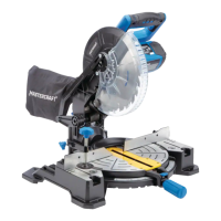
90° (0°) Bevel Adjustment
• Loosen bevel lock knob (1) and push the 0° stop pin
(2) in. Tilt the cutting arm completely to the right.
Tighten the bevel lock knob.
• Place a combination square (3) on the table with the
ruler against the table and the heel of the square
against the saw blade.
• If the blade is not 90° square with the table, loosen
the bevel lock knob, put a 4mm hex wrench into the
hole (4) located in the left side end of the arm holder,
turn the hex screw clockwise or counter-clockwise to
make the blade square to the table.
• Tighten bevel lock knob when alignment is achieved.
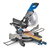
90° Bevel Pointer Adjustment
When the blade is exactly 90° to the table, loosen the
bevel indicator screw (1) using a Phillips screwdriver.
• Adjust bevel indicator (2) to the “0” mark on the bevel
scale and retighten the screw.
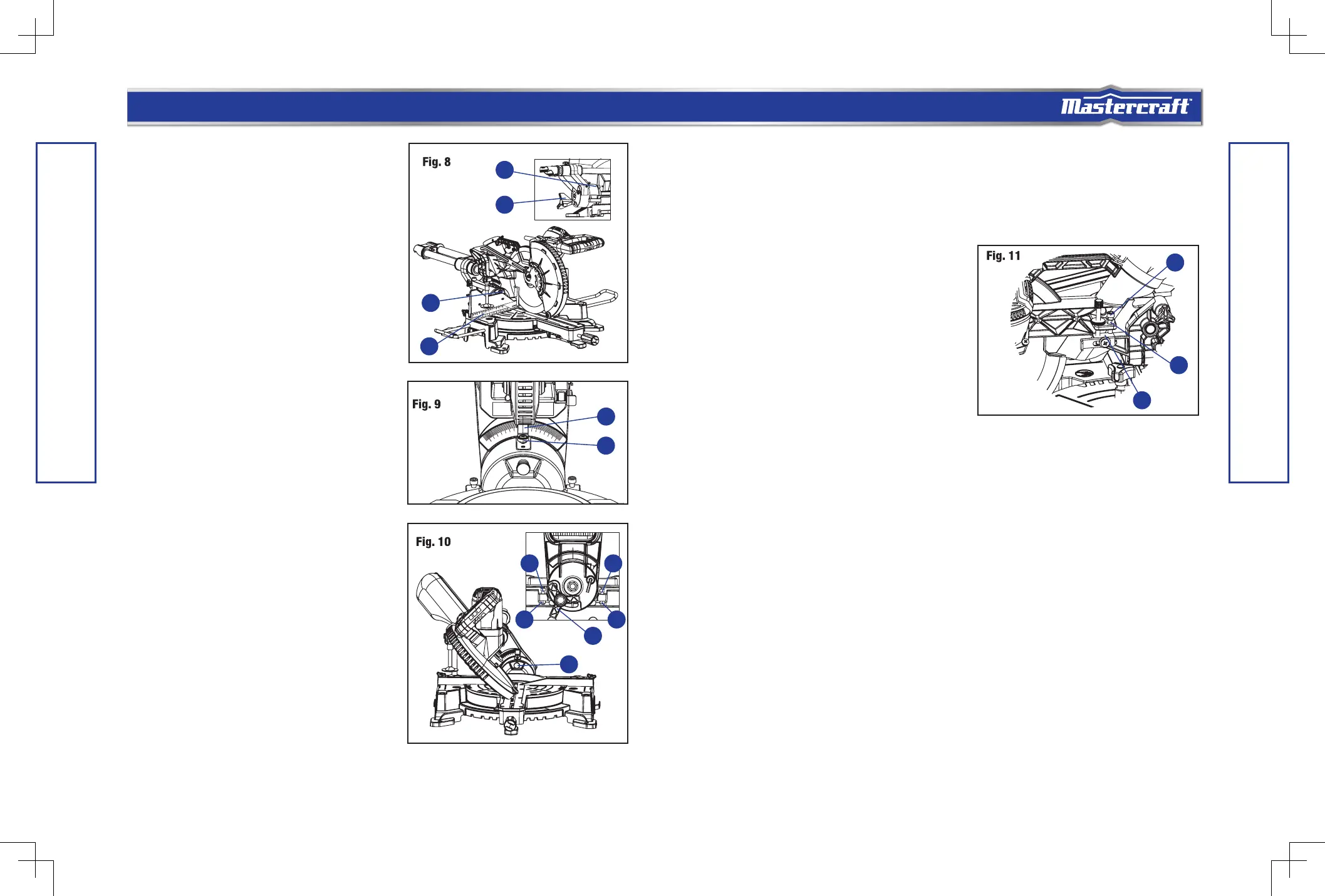
45° Bevel Adjustment LEFT AND RIGHT
• Loosen the bevel lock knob (1) and tilt the cutting
head completely to the left.
• Pull out the 0º stop pin (2).
• Loosen the bevel lock knob and tilt the cutting head
completely to the left. The mitre angle scale must be
at 0º.
• Using a combination square, check to see if the blade
is at a 45° angle to the table.
• If the blade is not at 45° to the table, tilt the cutting
arm to the right, loosen the lock nut (3) on the bevel
angle adjustment bolt (4) and use a 5 mm hex wrench
to adjust bolt depth in or out to increase or decrease
the bevel angle.
ASSEMBLY AND ADJUSTMENTS
• Tilt the cutting arm to the left to 45° bevel and recheck for alignment.
• Repeat above steps until the blade is at 45° to the table.
• Tighten bevel lock knob and lock nut when alignment is achieved.
• The right bevel 45° adjustment uses the same sequence as the left bevel adjustment, just adjusting
the adjustment bolt to 45° on the right.
MAXIMUM CUTTING DEPTH
The maximum depth travel of the cutting head was set at
the factory. Check to see that the blade does not extend
more than 11/16” (1.7 cm). below the table insert, and
does not touch the control arm throat or any part of the
base or table. If the maximum depth needs readjusting:
• Loosen the lock nut (1) to free the depth screw (2).
• Move the cutting head down until the blade extends
just 11/16” (1.7 cm). below the table insert.
• Adjust the depth screw to touch the stop plate (3),
then tighten the lock nut to secured the depth screw.
• Recheck the blade depth by moving the cutting head front to back through the full motion of a cut
along the control arm. If the blade touches the inside of the control arm, readjust the setting.
• When it is properly set, tighten the lock nut to lock the depth screw.
ASSEMBLY AND ADJUSTMENTS
1
2
2
1
3
3
1
2
4
3
4
1
4
2
3
 Loading...