22 23
model no. 055-6745-2 | contact us 1-800-689-9928
COMPOUND CUT
A compound cut is the combination of a mitre and a bevel
cut simultaneously.
• Adjust the lock-down pin to release the cutting head.
• Loosen the mitre handle (1). Lift up the positive stop
locking lever (2) and position the table at the desired
angle. The saw has positive stops at 0°, 15°, 22.5°,
31.6°, 45°, left and right. After getting the ideal mitre
angle, release the positive stop locking lever (2) and
lock the mitre handle (1).
• Loose the bevel lock knob (3) to set the bevel angle.
• Adjust the cutting head to get the ideal bevel angle.
Once the cutting head has been set at the desired
angle, securely tighten the bevel lock knob (3).
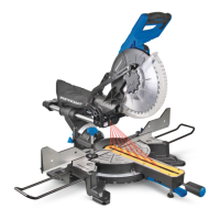
SLIDING CARRIAGE SYSTEM
• For chop cutting operations on small workpieces, slide
the cutting head completely toward the rear of the unit
and tighten the carriage lock knob (1).
• To cut wide boards up to 12” (30.5 cm), the carriage
lock knob must be loosened to allow the cutting head
to slide freely.
Slide stop
The slide stop control positions your saw rails so that the
largest possible vertical moldings can be cut. Push the
moving plate (1) which connects with the stop pin (2) to the
right. Slide the carriage until the pin hits the guide fence.
ALWAYS TIGHTEN THE RAIL LOCK KNOB WHEN USING
THE SLIDE STOP TO PREVENT THE SLIDE SYSTEM FROM
MOVING UNINTENTIONALLY.
1
•
Clamp the workpiece with the work clamp if
necessary.
Follow all of the cutting instructions for the type of cut to
be performed.
DRY RUN
For safe operation, it’s necessary to know where the blade
will contact the workpiece during the cutting process.
Always perform the simulated cutting process with the
switch off to check and understand the projected path of
the saw blade. Adjust the work clamps and fences to avoid
any contact with the lower guard and cutting action.
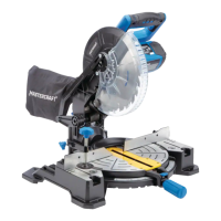
MITRE CUT
•
When a mitre cut is required, unlock the table by
turning the mitre handle (1) counter-clockwise.
• While holding the mitre handle, lift up on the positive
stop locking lever (2).
• Rotate the table to the right or left with the mitre
handle.
• When the table is in the desired position, as shown
on the mitre scale (3), release the positive stop
locking lever and tighten the mitre handle. The table
is now locked at the desired angle. Positive stops are
provided at 0°, 15°, 22.5°, 31.6° and 45°.
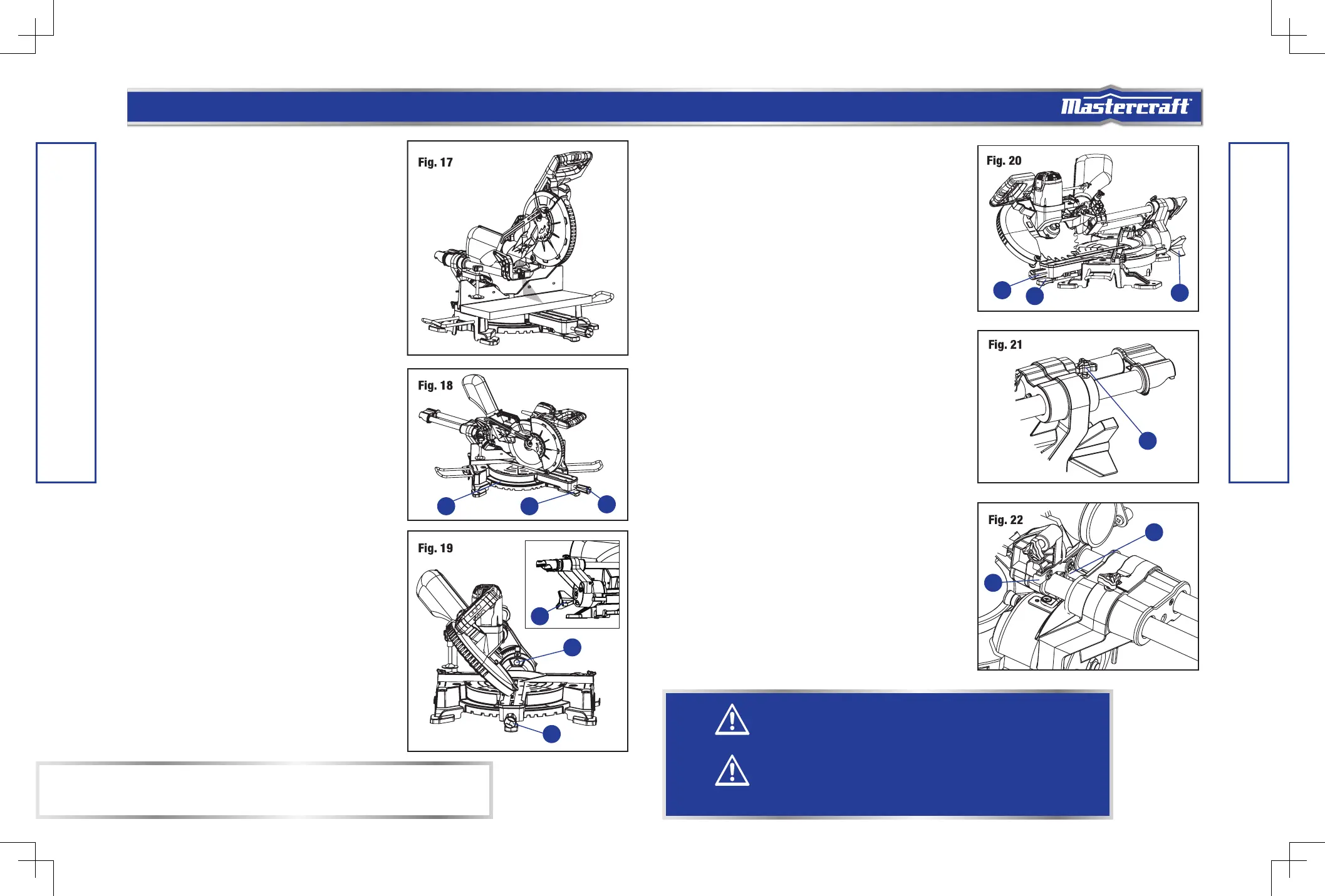
BEVEL CUT
• Make sure that the table is at 0° and lock the mitre
lock handle (1). Adjust the lock-down pin to release
the cutting head.
• Loosen the bevel lock knob (2) by turning it clockwise
and adjust the cutting head to get the desired angle.
Please note that when beveling the cutting head to
the right, you should first pull out the 0° stop pin (3),
otherwise the cutting head won’t be beveled to the
right. The blade can be positioned at any angle, from
a 90° straight cut (0° on the scale) to a 45° left / right
bevel.
OPERATING INSTRUCTIONS
OPERATING INSTRUCTIONS
IMPORTANT:
Always tighten the mitre table lock handle before performing every cutting operation.
CAUTION!
To reduce the risk of injury, return carriage to the full rear position after each crosscut operation.
CAUTION!
Always use a work clamp to maintain control and reduce the risk of workpiece damage and
personal injury.
1
2
3
2
3
1
3
2
1
1
2
 Loading...