16 17
model no. 055-6762-0 | contact us 1-800-689-9928
Mitre Angle Pointer Adjustment
(Fig. 6)
• Move the table to the 0° positive stop.
• Loosen the screw (4) that holds the indicator with a Phillips screwdriver.
• Adjust the indicator (3) to the 0° mark and retighten the screw.
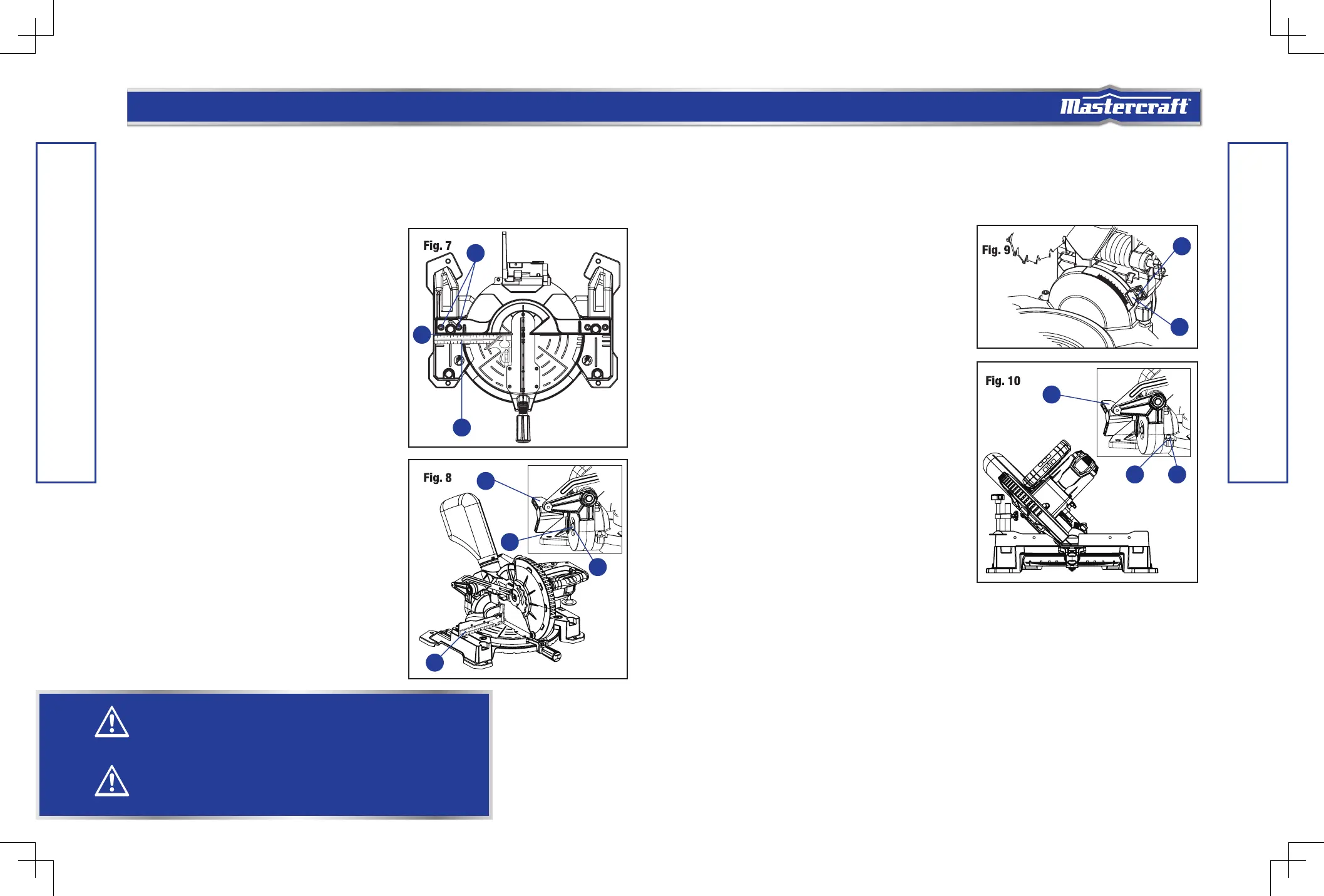
ADJUSTING FENCE SQUARENESS (Fig. 7)
• Lower the cutting head and lock in position.
• Using a square (1), lay the heel of the square against
the blade and the ruler against the fence (2) as shown.
• Loosen the four fence locking bolts (3) with a 6 mm
hex wrench.
• Adjust the fence 90° to the blade and tighten the two
fence locking bolts.
• After fence has been aligned, make a cut at 90° using
a scrap piece of wood and check squareness on the
piece. Readjust if necessary.
BEVEL STOP ADJUSTMENT
This tool is carefully adjusted and aligned at the factory,
but rough handling may have affected the alignment. If
your tool is not aligned properly, perform the following as
needed.
90° (0°) Bevel Adjustment (Fig. 8)
• Loosen bevel lock knob (1) and tilt the pivot arm
completely to the right. Tighten the bevel lock knob.
• Place a combination square (2) on the mitre table with
the ruler against the table and the heel of the square
against the saw blade.
•
If the blade is not 90° square with the table, loosen the bevel lock knob, tilt the cutting head to the left,
loosen the locknut (4) and turn the bevel angle adjustment bolt (3) in or out with a 4 mm hex wrench
until the blade is square with the table.
• Tilt the pivot arm back to the right at 90° (0°) bevel and recheck for alignment.
• Repeat steps if further adjustment is needed.
• Tighten bevel lock knob and locknut (4) when
alignment is achieved.
90° Bevel Pointer Adjustment (Fig. 9)
When the blade is exactly 90° to the table, loosen the bevel
indicator screw (1) using a star-head screwdriver.
• Adjust bevel indicator (2) to the “0” mark on the bevel
scale and retighten the screw.
45° Bevel Adjustment (Fig. 10)
• Loosen the bevel lock knob (1) and tilt the cutting
head completely to the left.
• Using a combination square, check to see if the blade
is at a 45° angle to the table.
• If the blade is not at 45° to the mitre table, tilt the
pivot arm to the right, loosen the locknut (2) on the
bevel angle adjustment bolt (3) and use a 4 mm hex
wrench to the adjust bolt depth in or out to increase or
decrease the bevel angle.
• Tilt the cutting arm to the left to 45° bevel and
recheck for alignment.
• Repeat steps until the blade is at 45° to the mitre
table.
• Tighten bevel lock knob and locknut when alignment is achieved.
ASSEMBLY AND ADJUSTMENTS
ASSEMBLY AND ADJUSTMENTS
WARNING!
To avoid injury from an accidental start, make sure the switch is in the OFF position and the plug
is not connected to the power source outlet.
WARNING!
To reduce the risk of injury, wear safety goggles or glasses with side shields.
1
2
2
1
4
3
1
2
3
2
1
3
 Loading...