model no. 058-8195-2 | contact us 1-800-689-9928
ASSEMBLY INSTRUCTIONS
ASSEMBLY PREPARATION
8
9
Different materials require different shielding gas when MIG welding. Refer to the set-up chart inside
the wire drive compartment.
Mild steel: Use 75% argon and 25% CO for reduced spatter and reduced penetration for thinner
materials. Use CO for deeper penetration and increased spatter.
Note: Do not use argon gas concentrations higher than 75% on steel. The result will be extremely
poor penetration, porosity, and brittleness of weld.
Stainless steel: Use a mixed gas consisting of helium, argon, and CO .
Aluminum or bronze: Use 100% argon.
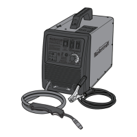
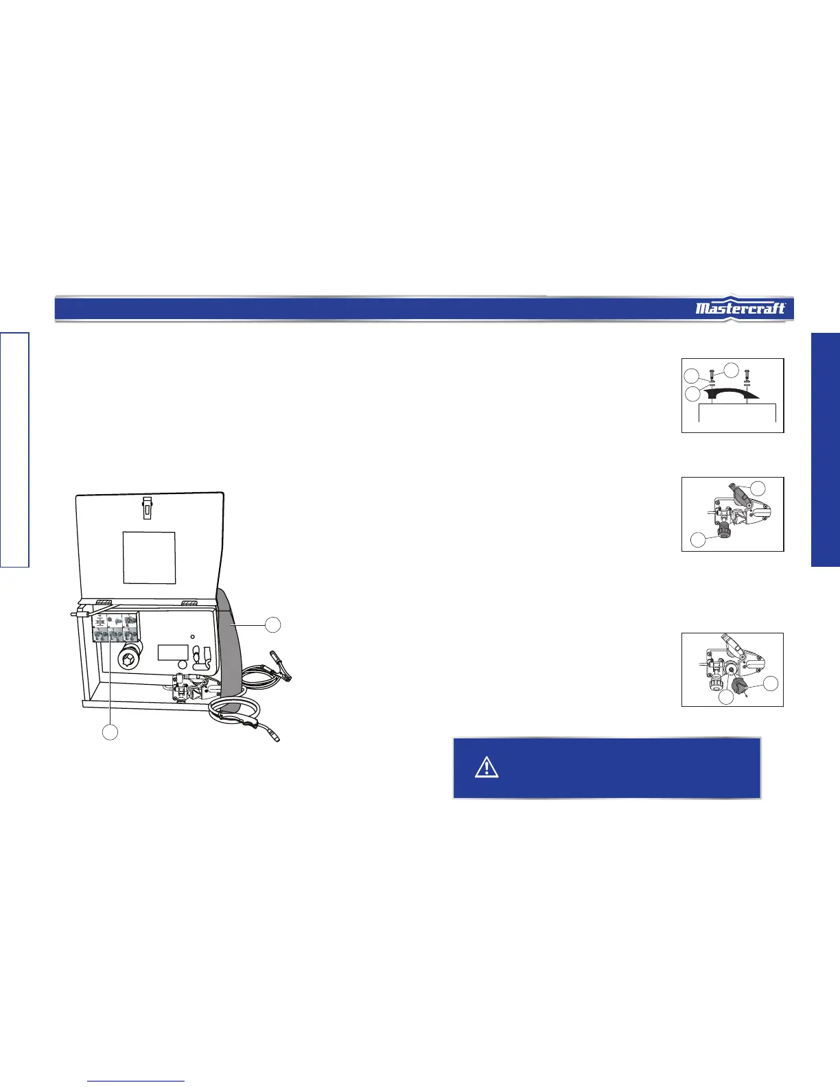
The wire drive compartment houses wire feed components (1) such as wire feeder and spool hub,
and includes a set-up chart (2).
GAS SELECTION
WIRE DRIVE COMPARTMENT
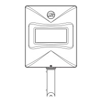
Installing the handle:
Installing the wire roller:
1
2
2
3
MC-588195-02
1
2
1
MC-588195-03
1. Line up the holes in the handle with the
holes on the top of the welder.
2. Place a lock washer (1) and a washer (2)
onto the welder handle screws.
3. Insert a screw with the washers through
the holes on the handle and into the top
of the welder, and tighten the screw
(fig. A).
1. Open the wire drive compartment.
2. Remove the drive tension by loosening
the drive tension adjusting knob (1) and
lifting the drive tension adjustor and
drive tension arm (2) away from the
drive roller (fig. B).
3. Put an end of the wire into the hole on
outside edges of the wire spool and
bend it over to hold the wire in place.
Remove the wire spool from the wire
drive compartment.
4. Rotate the drive roller cap (1)
counter-clockwise and remove it from the
drive roller (2) (fig. C).
WARNING!
-
Note: If the wire is already installed in the welder, roll the wire back onto the wire spool by manually
rotating the wire spool clockwise. Do not allow the wire to come out of rear end of the inlet guide
tube.
6.
0
1
2
MC-588195-04
 Loading...